Domain 2.5 | Network Access — 20% of exam
Learning Objectives
By the end of this lesson, you will be able to:
- Explain why Spanning Tree Protocol exists and what happens without it
- Describe how root bridge election works using Bridge ID comparison
- Identify Rapid PVST+’s three port states and explain why they enable faster convergence
- Distinguish root ports from designated ports in a redundant topology
- Compare root guard, loop guard, BPDU guard, and BPDU filter, and identify which failure mode each solves
Key Terms
| Term | Definition |
|---|---|
| STP | Spanning Tree Protocol; prevents Layer 2 loops by logically blocking redundant paths |
| Bridge ID | A switch’s priority value combined with its MAC address, used in root bridge election |
| Root bridge | The switch with the lowest Bridge ID, serving as the reference point for the spanning tree |
| Root port | On a non-root switch, the port with the best path back to the root bridge |
| Designated port | The port on a network segment responsible for forwarding traffic toward the root |
| BPDU | Bridge Protocol Data Unit; the message switches exchange to run spanning tree calculations |
Explanation
The Problem: What Happens Without STP
EtherChannel showed one deliberate, controlled way to have redundant physical links between switches without creating a loop — by bundling them into a single logical interface. But not every redundant path in a real network is a bundled EtherChannel; many redundant topologies exist simply because multiple switches are physically interconnected for genuine resilience, without those specific links being bundled together at all. Left completely unmanaged, this kind of topology creates a genuine, severe problem.
Recall from the earlier lesson on switching concepts that switches flood frames with unknown destinations, broadcasts, and unknown multicast out every port except the one they arrived on. In a topology with a genuine Layer 2 loop — multiple active paths between the same two switches, with no mechanism preventing it — a single flooded frame doesn’t just reach its destination once.
It circulates continuously around the loop, and every switch it passes through floods it out its other ports as well, since each successive circuit still looks like an unknown-destination or broadcast frame to each switch encountering it. The traffic doesn’t just persist — it multiplies, with each loop iteration spawning additional copies across every switch in the loop. This is a broadcast storm, and it’s genuinely severe: an unmanaged Layer 2 loop can consume 100% of available bandwidth and processing capacity across an entire switched network within seconds, effectively taking the whole network down.
STP exists specifically to prevent this, by logically blocking redundant paths so that, at any given moment, only one active path exists between any two points in the topology — the other paths remain physically connected but logically held in reserve, ready to activate automatically if the active path fails, without ever creating an active loop in normal operation.
Root Bridge Election: The Foundation Everything Else Builds On
Before any port can be assigned a specific role, every switch running STP needs to agree on a single reference point the entire topology calculates its paths relative to. That reference point is the root bridge.
Every switch has a Bridge ID, composed of two parts: a priority value (a configurable number, defaulting to 32768 on most Cisco switches) and the switch’s own MAC address. The switch with the numerically lowest Bridge ID becomes the root bridge — comparing priority first, and only falling back to comparing MAC address as a tiebreaker if two switches happen to share the identical priority value.
Worked example: three switches, SW1, SW2, and SW3, all running with the default priority of 32768. Since all three share the identical priority, the tiebreaker falls to MAC address — whichever switch has the numerically lowest MAC address wins the root bridge election, entirely by default, without any administrator having deliberately chosen it.
This is worth flagging directly: leaving root bridge election entirely to default priority values means the root bridge is essentially chosen by which switch happens to have the lowest MAC address — a somewhat arbitrary outcome from a network design perspective, which is exactly why real deployments commonly configure priority manually on a deliberately chosen switch (typically a core or distribution-layer switch with strong processing capacity and reliable uptime) to ensure it becomes root, rather than leaving the outcome to an essentially random MAC address comparison.
Worth flagging as genuinely counterintuitive, since it trips up newcomers: lower numerically wins the root bridge election — the opposite of the “higher number wins” assumption that might feel more natural coming from other contexts. A switch specifically configured with a lower priority (say, 4096 instead of the default 32768) is deliberately making itself more likely to become root, not less.
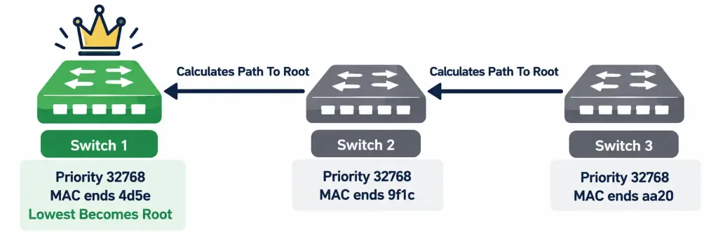
Once the root bridge is established, every other switch calculates its own best (lowest-cumulative-cost) path back to it — cost here being based primarily on link bandwidth, with faster links carrying a lower cost value, conceptually similar in spirit to how OSPF’s cost metric (covered in Domain 3) also favors higher-bandwidth paths, even though the two protocols calculate their specific cost values differently.
Rapid PVST+ Port States: Where “Rapid” Actually Comes From
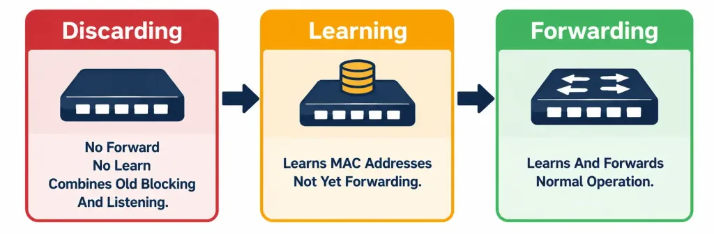
Every port participating in spanning tree exists in one of three states under Rapid PVST+ — and understanding exactly why there are three states here, rather than the four states legacy 802.1D used, is precisely what explains the “Rapid” part of this protocol’s name.
- Discarding — the port neither forwards frames nor learns MAC addresses. This single state combines what legacy 802.1D handled as two separate states — Blocking and Listening — into one unified state under Rapid PVST+. This consolidation is a direct, deliberate contributor to Rapid PVST+’s faster convergence compared to legacy 802.1D: fewer distinct states to transition through means less total time spent transitioning before a port reaches a stable, final state.
- Learning — the port learns MAC addresses (building its entry in the MAC address table, exactly as covered in the earlier switching concepts lesson) but doesn’t yet forward frames. This is a genuinely transitional state, not a final resting state a port stays in indefinitely.
- Forwarding — full normal operation: the port both learns addresses and forwards traffic. This is the state every actively-used port ultimately needs to reach.
Why the Discarding-Learning-Forwarding sequence itself matters, not just the individual state definitions: a port doesn’t jump straight to forwarding traffic the moment it comes up. It first sits in Discarding (preventing any possibility of temporarily contributing to a loop while the topology is still being calculated), then transitions to Learning (starting to build MAC table knowledge without yet risking a loop by actually forwarding traffic), and only then transitions to Forwarding once the topology calculation has genuinely stabilized. This staged approach is a deliberate safety mechanism — the temporary cost of a brief delay before full forwarding begins is considered well worth avoiding the far more serious risk of a transient loop during the topology’s own calculation process.
Root Port vs. Designated Port: Two Distinct Roles, Easy to Confuse
Once the root bridge is elected, every other switch and every network segment needs specific ports assigned specific roles, and these two role names — root port and designated port — are worth distinguishing precisely, since they’re genuinely different concepts despite both involving “which port actually forwards traffic toward the root.”
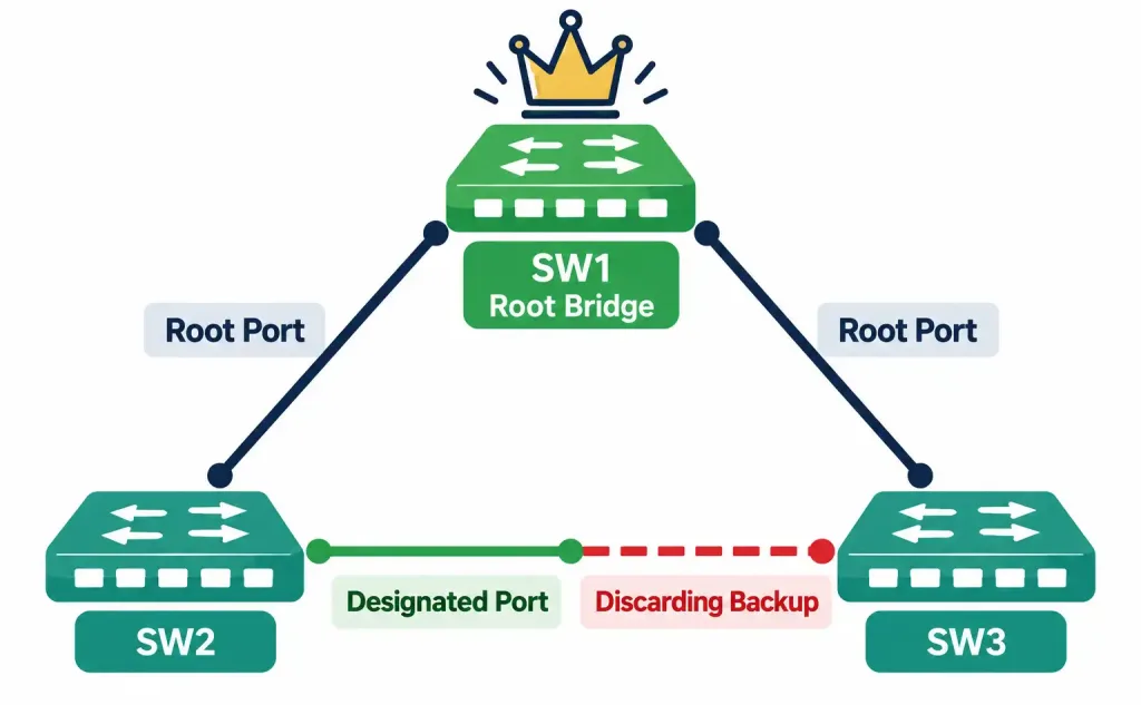
Root port: on each non-root switch, exactly one port — the one with the best (lowest cumulative cost) path back to the root bridge — is designated the root port. Every non-root switch has exactly one root port; the root bridge itself has none, since it has no need to find a path back to itself.
Designated port: on each network segment (a link between two switches, or a shared media segment), exactly one port is responsible for forwarding traffic toward the root — the designated port for that specific segment. Every segment has exactly one designated port, even segments the root bridge itself is directly connected to (where the root bridge’s own port on that segment is, by definition, the designated port, since it’s already at the root).
Worked example, tying both roles together in a concrete three-switch topology: SW1 is the root bridge. SW2 and SW3 both connect directly to SW1, and SW2 and SW3 are also connected to each other, forming a redundant triangle.
- SW2’s port connecting to SW1 becomes SW2’s root port — SW1 is the root, and this is SW2’s best path to it.
- SW3’s port connecting to SW1 becomes SW3’s root port — for the identical reason.
- On the segment between SW1 and SW2, SW1’s own port is the designated port for that segment, since SW1 is already at the root.
- On the segment between SW1 and SW3, SW1’s own port is again the designated port for that specific segment.
- On the segment between SW2 and SW3 — the “extra” redundant link forming the triangle — one of the two switches’ ports on that segment becomes the designated port (typically whichever has the lower cumulative cost back to the root, or the lower Bridge ID as a tiebreaker), and the other switch’s port on that same segment ends up in the Discarding state, since a segment can only have one designated port, and this specific link isn’t needed for the currently active, loop-free topology.
This last point is worth sitting with specifically: the “blocked” (Discarding) port in this scenario isn’t broken or misconfigured — it’s functioning exactly as intended, held in reserve specifically so that if the SW1-to-SW2 or SW1-to-SW3 link fails, this currently-Discarding port on the SW2-SW3 segment can transition to Forwarding, providing the exact redundancy this topology was physically built to offer in the first place.
The Four Protection Features: Distinct Problems, Similar-Sounding Names
This is precisely where exam confusion tends to concentrate, since these four features all sound conceptually related — they’re all “spanning tree security/stability mechanisms” — but each solves a genuinely distinct, specific failure mode.
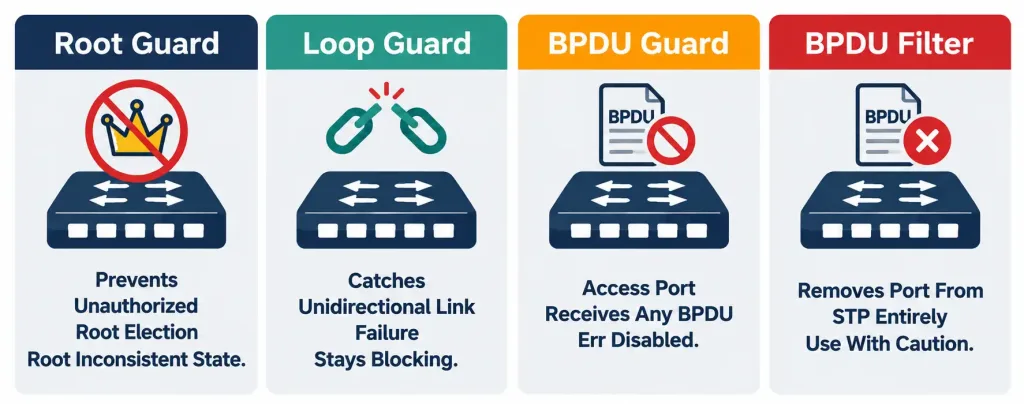
Root guard protects against an unauthorized or unintended device becoming the root bridge. It’s placed on ports facing switches that should never become root — typically access-layer ports facing switches that are deliberately meant to stay subordinate in the topology. If a superior BPDU (one advertising a lower Bridge ID than the current root, meaning the sending device is attempting to become the new root) is received on a root-guard-protected port, that port is placed into a root-inconsistent state — refusing to accept this unauthorized topology change, rather than allowing the connected device to actually become root. The port automatically recovers once superior BPDUs stop being received.
Loop guard protects against a specific, subtler failure mode: a unidirectional link failure, where a port stops receiving BPDUs from its neighbor but the link itself doesn’t actually go physically down. Without loop guard, a port in this specific situation could incorrectly conclude the neighbor (and any competing path) has disappeared, and transition to Forwarding — creating a genuine loop, since the neighbor switch on the other end may still be actively forwarding traffic on what it still considers a valid, functioning link. Loop guard specifically keeps a port in a blocking state during this ambiguous condition until BPDUs genuinely resume, rather than assuming their absence means it’s now safe to forward.
BPDU guard, typically applied to access ports — where only end-user devices are ever supposed to connect — takes a specifically aggressive stance: if a BPDU is ever received on that port at all, meaning an unauthorized switch has been connected where only an end-user device was ever expected, BPDU guard immediately err-disables the port entirely, shutting it down until an administrator manually intervenes. This is a deliberately strict, no-tolerance response, appropriate specifically because a legitimate end-user device (a PC, a printer, a phone) should never be sending BPDUs at all — any BPDU appearing on an access port is treated as a hard indicator that something is present that shouldn’t be there.
BPDU filter suppresses BPDU transmission and processing on a port entirely, effectively removing that port from spanning tree calculations altogether. This one genuinely needs to be used carefully, since misuse can actively create the exact loop condition BPDU-based mechanisms exist to prevent, rather than protecting against one — if BPDU filtering is applied somewhere a genuine switch (rather than only an end device) ends up connected, that connection’s BPDUs are never processed at all, meaning spanning tree loses its ability to detect and prevent a loop specifically through that connection.
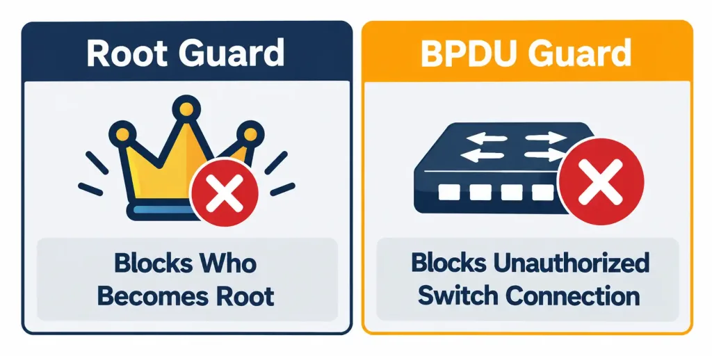
The specific, exam-tested distinction worth memorizing verbatim, since it’s called out directly as a common point of confusion: root guard protects against an unauthorized device becoming root — it’s concerned specifically with who gets to be root. BPDU guard protects access ports from having an unauthorized switch connected at all — it’s concerned with whether a switch should be there in the first place, regardless of whether that switch would ever actually win a root election. These solve genuinely different problems despite the similar “BPDU-related protection feature” framing, and the exam frequently tests whether you can correctly match a described symptom to the right one of these two specifically.
Per-VLAN Operation: What the “PVST” in Rapid PVST+ Actually Means
PVST stands for Per-VLAN Spanning Tree, and this isn’t a minor naming detail — it describes a genuinely important operational characteristic. Rather than running a single spanning tree calculation for the entire switched network regardless of VLAN, Rapid PVST+ runs a completely separate spanning tree instance for each individual VLAN.
Why this matters practically: different VLANs can have entirely different root bridges, and consequently, different blocked (Discarding) links, even across the exact same physical topology. This isn’t just a theoretical possibility — it’s a genuinely useful real-world design technique. A network administrator can deliberately configure SW1 as the root bridge for VLAN 10 while configuring SW2 as the root bridge for VLAN 20 (on the same physical topology), causing VLAN 10’s traffic to naturally flow through one physical path while VLAN 20’s traffic flows through a different one — achieving genuine load distribution across otherwise-redundant physical links, rather than having every single VLAN’s traffic funnel through the identical single active path a single, network-wide spanning tree instance would otherwise produce.
Worked example: a network with two core switches and two redundant uplinks between them, carrying both VLAN 10 and VLAN 20. Under a single, VLAN-unaware spanning tree, one of the two uplinks would sit entirely idle in Discarding state for all traffic, regardless of VLAN — wasting half the available redundant capacity under normal conditions. Under Rapid PVST+’s per-VLAN operation, deliberately setting different root bridge priorities per VLAN lets VLAN 10 actively use one uplink while VLAN 20 actively uses the other, with each uplink serving as the standby backup for the other VLAN’s traffic — genuinely using both physical links simultaneously under normal conditions, rather than leaving one link’s capacity completely unused until a failure occurs.
Verifying Spanning Tree Operation
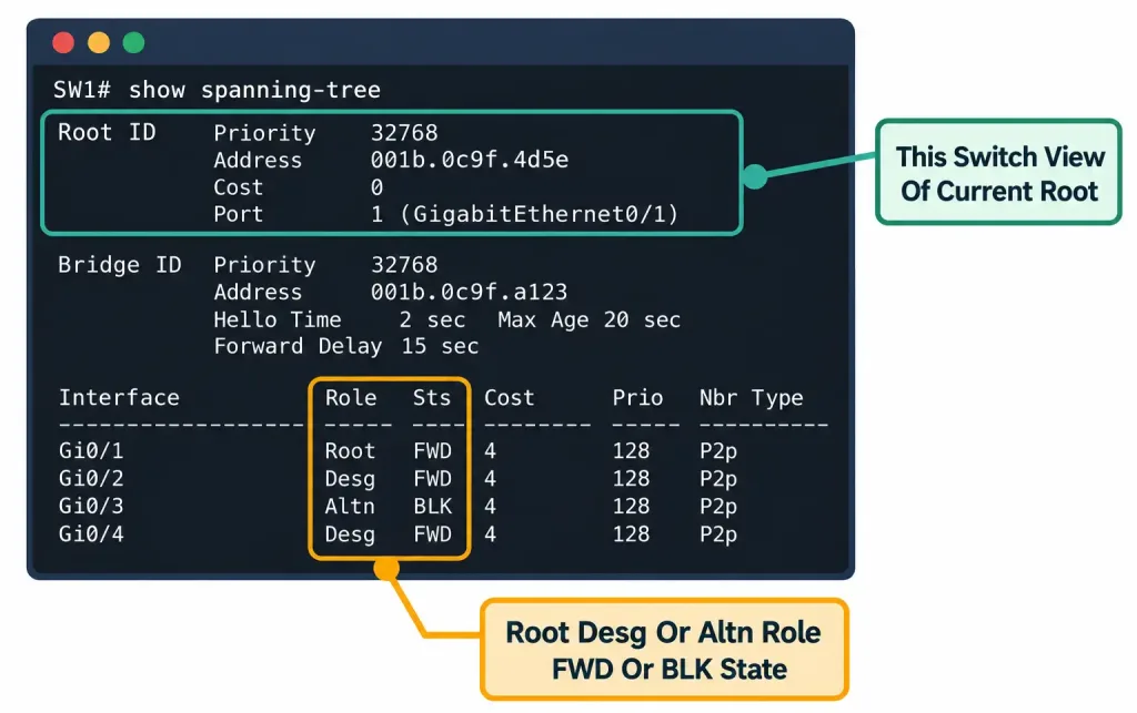
Switch# show spanning-tree

VLAN0010
  Spanning tree enabled protocol rstp
  Root ID    Priority    24586
             Address     0019.aa2f.b100
             Cost        4
             Port        1 (GigabitEthernet0/1)

  Bridge ID  Priority    32778  (priority 32768 sys-id-ext 10)
             Address     001a.2b3c.4d5e

Interface    Role   Sts   Cost   Prio.Nbr   Type
------------ ------ ---   ----   --------   --------
Gi0/1        Root   FWD   4      128.1      P2p
Gi0/2        Desg   FWD   4      128.2      P2p
Gi0/3        Altn   BLK   4      128.3      P2p
Reading this output field by field: the top section identifies the Root ID — this switch’s view of who the current root bridge is, its priority, MAC address, the cost to reach it, and which local port leads there. The Bridge ID section shows this switch’s own identity, for comparison against the root. The interface table below shows each port’s Role (Root, Designated, or in this case Altn — an alternate port held in reserve) and current Sts (status/state — FWD for Forwarding, BLK for a Discarding/blocking port, consistent with the port-state concepts covered earlier in this lesson).
Worth noting specifically about the output above: the priority shown, 32778, isn’t simply the default 32768 — it reflects the default priority plus a small VLAN-specific extension value (the “sys-id-ext” of 10 in this case, corresponding to VLAN 10), which is exactly how Rapid PVST+ maintains a genuinely distinct, per-VLAN Bridge ID for each VLAN’s separate spanning tree instance, directly reflecting the per-VLAN operation covered above.
Configuring the protection features covered earlier, for reference:
Switch(config-if)# spanning-tree guard root
Switch(config-if)# spanning-tree guard loop
Switch(config-if)# spanning-tree bpduguard enable
Switch(config-if)# spanning-tree bpdufilter enable
Each of these is applied per-interface, matching exactly where each feature is actually meant to be deployed — root guard and BPDU guard typically on ports facing devices that should never contribute additional switches to the topology, loop guard typically on point-to-point links where unidirectional failure is a genuine physical possibility.
Common Misconceptions Worth Correcting Directly
“A lower Bridge ID is a worse switch, since lower usually means less capable.” As covered above, this instinct runs backwards for root bridge election specifically — a lower Bridge ID wins the election, meaning it becomes root, and administrators deliberately lower a chosen switch’s priority specifically to make it more likely, not less, to become root.
“A Discarding port is broken or malfunctioning.” As covered in both the port-state and root/designated-port discussions above, a port in Discarding state is functioning exactly as intended, held in reserve specifically to provide the redundancy the physical topology was built to offer — it isn’t an error condition to fix.
“Root guard and BPDU guard are basically the same feature with different names.” As covered directly above, this is precisely the confusion the exam specifically tests — root guard is about who becomes root; BPDU guard is about whether a switch should be connected to this specific port at all. They respond to different triggers and produce different outcomes (root-inconsistent state versus err-disabled port).
“BPDU filter is always a safe, protective feature to apply, similar to the other three.” As covered above, this is specifically the one exception among the four — misusing BPDU filter can actively create a loop rather than prevent one, since it removes a port from spanning tree’s loop-detection capability entirely, unlike the other three features, which all actively reinforce loop prevention rather than potentially undermining it.
“Rapid PVST+ runs one single spanning tree calculation for the whole network, just like older STP implementations.” As covered in the per-VLAN operation section, this is specifically what distinguishes PVST-based implementations — a separate instance runs per VLAN, not one unified calculation across the entire network regardless of VLAN.
Frequently Asked Questions
Can the root bridge election outcome be predicted reliably without checking priority configuration directly?
Not reliably, if priorities haven’t been deliberately configured — with all switches at default priority, the outcome depends on MAC address comparison, which isn’t something you’d typically know or predict in advance without checking. This is exactly why deliberately configuring root bridge priority is considered a best practice rather than leaving the outcome to default behavior.
What is a superior BPDU, specifically?
A BPDU advertising a lower Bridge ID than the one the receiving switch currently considers root — meaning the sending device is claiming it should become the new root bridge instead. This is precisely the condition root guard watches for and blocks on a protected port.
Does BPDU guard apply to trunk ports the same way it applies to access ports?
BPDU guard is specifically designed for and typically applied to access ports, where legitimate end-user devices (which never send BPDUs) are expected to connect — applying it to a trunk port connecting two legitimate switches would err-disable that port immediately upon the normal, expected exchange of BPDUs between two switches that are both genuinely supposed to be there.
How quickly does a port recover from root guard’s root-inconsistent state once the superior BPDUs stop?
Recovery happens automatically once superior BPDUs are no longer received, without requiring manual administrator intervention — a genuine, meaningful difference from BPDU guard’s err-disabled state, which requires manual re-enabling (or a specific auto-recovery configuration) before the port becomes usable again.
Why would per-VLAN root bridge placement ever need to be manually configured, rather than trusting the default election process?
Because, as covered above, leaving every VLAN to elect its root bridge purely by default priority and MAC address comparison would very likely result in the identical switch becoming root for every VLAN simultaneously — missing the genuine load-distribution opportunity that deliberately varying root bridge placement per VLAN specifically provides.
Rapid PVST+, Root Bridge & STP Protection: Practice Quiz
Test your knowledge of spanning tree operation, root bridge election, and STP protection features.
Summary
- STP prevents broadcast storms by logically blocking redundant Layer 2 paths, keeping only one active path between any two points while holding others in reserve.
- Root bridge election compares Bridge ID (priority plus MAC address); the numerically lowest wins, which is counterintuitive to a “higher is better” assumption.
- Rapid PVST+’s three port states — Discarding, Learning, Forwarding — consolidate legacy 802.1D’s four states into three, directly enabling faster convergence.
- Every non-root switch has exactly one root port; every network segment has exactly one designated port; a Discarding port on a redundant link is functioning as intended, not malfunctioning.
- Root guard, loop guard, BPDU guard, and BPDU filter each solve a distinct failure mode — root guard prevents unauthorized root elections, loop guard catches unidirectional link failures, BPDU guard shuts down access ports receiving any BPDU, and BPDU filter removes a port from spanning tree entirely (requiring careful use, since misuse can create loops).
- Rapid PVST+ runs a separate spanning tree instance per VLAN, allowing deliberate root bridge placement per VLAN to achieve genuine load distribution across redundant physical links.
- show spanning-tree verifies root bridge identity, port roles, and port states on a per-VLAN basis.