Domain 2.1 | Network Access — 20% of exam
Learning Objectives
By the end of this lesson, you will be able to:
- Explain what a VLAN actually does at the broadcast domain level
- Configure a VLAN and assign access ports to it on Cisco IOS
- Verify VLAN configuration using show commands
- Explain why spanning a VLAN across multiple switches requires trunking, and identify the common pitfall that breaks this
Key Terms
| Term | Definition |
|---|---|
| VLAN | Virtual LAN; a logical broadcast domain configured independently of physical switch boundaries |
| Broadcast domain | The set of devices that receive a given broadcast frame |
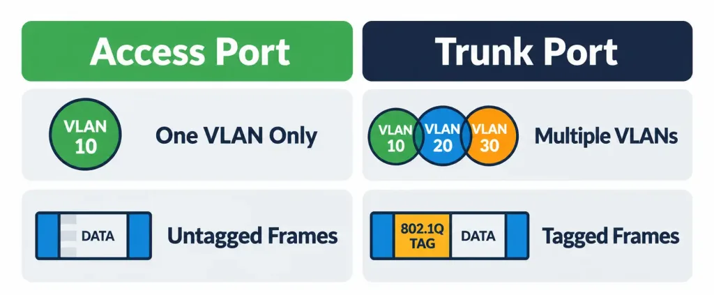
| Access port | A switch port assigned to exactly one VLAN, carrying untagged traffic for that VLAN only |
| Trunk port | A switch port carrying tagged traffic for multiple VLANs between switches (full detail in the next lesson) |
| VLAN ID | The numeric identifier assigned to a specific VLAN |
| VTP | VLAN Trunking Protocol; a legacy mechanism for synchronizing VLAN databases across switches |
Explanation
Starting Domain 2: From Fundamentals to Access
Domain 1 covered the vocabulary and mechanics underlying every network — addressing, cabling, and, in the final Domain 1 lesson on switching concepts, exactly how a switch learns and forwards frames. Domain 2 (Network Access) builds directly on that foundation, covering how switches are actually organized and connected to build real, functional campus networks. VLANs are the right place to start, since nearly everything else in this domain — trunking, EtherChannel, spanning tree — exists specifically to support or protect VLAN-based network designs.
The Problem VLANs Actually Solve
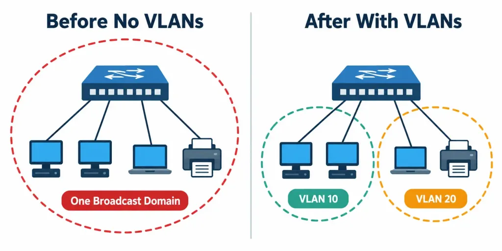
Before VLANs existed as a practical, widely available technology, achieving logical separation between different groups of devices meant genuine physical separation — a separate switch, entirely, for each group that needed its own isolated broadcast domain. A company wanting to keep its Sales and Engineering departments on separate broadcast domains would need to buy, cable, and maintain two entirely separate physical switches, even if both departments sat in the same building, used a fraction of a single switch’s actual port capacity, and had no real reason to require separate hardware beyond the logical separation itself.
A VLAN (Virtual LAN) solves this by letting a single physical switch — or, as this lesson covers, a set of interconnected physical switches — be logically divided into multiple, separate broadcast domains entirely through configuration, with no additional physical hardware required. Recall that broadcast frames get flooded to every port on a switch by design. A VLAN changes the scope of that flooding: broadcast traffic within one VLAN floods only to other ports in that same VLAN, never to ports assigned to a different VLAN on the same physical switch, even though they’re all plugged into identical physical hardware.
This has a direct, important consequence worth stating explicitly: devices in different VLANs cannot communicate with each other at all without a Layer 3 device (a router, or a Layer 3 switch, both covered in earlier lessons) actively routing traffic between them — even if those two devices are physically connected to ports on the exact same switch, sitting right next to each other in the same equipment rack. VLAN separation is a genuine, enforced logical boundary, not merely an organizational label applied on top of otherwise-unrestricted connectivity.
Basic VLAN Configuration
Creating a VLAN and assigning a port to it involves two genuinely distinct steps, worth understanding as separate actions even though they’re often performed together in quick succession.
Switch(config)# vlan 20
Switch(config-vlan)# name Sales
Switch(config-vlan)# exit
Switch(config)# interface GigabitEthernet0/1
Switch(config-if)# switchport mode access
Switch(config-if)# switchport access vlan 20
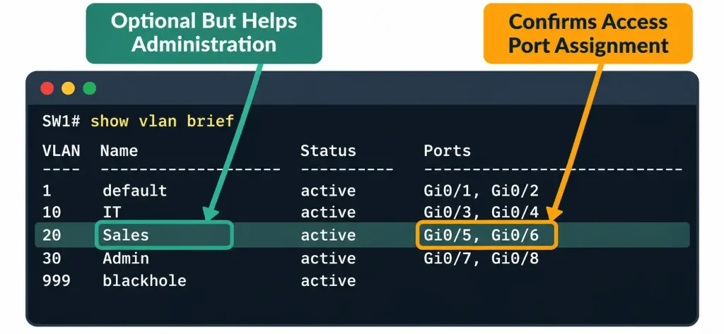
Step one: create the VLAN itself, entering VLAN configuration mode and optionally assigning it a human-readable name. The name command is genuinely optional — a VLAN functions identically whether or not it has a friendly name assigned — but naming VLANs meaningfully (Sales, rather than leaving it to default to something like VLAN0020) makes ongoing administration and troubleshooting considerably easier, particularly on a switch with many VLANs configured simultaneously.
Step two: assign a specific port to that VLAN, first explicitly setting the port to access mode (switchport mode access), then specifying which VLAN it belongs to (switchport access vlan 20). An access port carries traffic for exactly one VLAN, and it does so using untagged frames — devices connected to an access port have no awareness of VLANs at all; from their perspective, they’re simply connected to an ordinary network, with the switch handling all VLAN-related logic entirely transparently to the connected device itself.
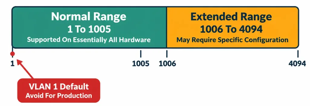
VLAN ID ranges worth knowing: the normal range covers VLAN IDs 1 through 1005, supported on essentially all Cisco switching hardware without any special configuration. The extended range covers VLAN IDs 1006 through 4094, requiring specific switch configuration (VTP transparent mode, covered briefly below) to use on older platform generations, though modern switches generally support the full extended range without this historical limitation being a practical concern.
VLAN 1 deserves a specific mention: it’s the default VLAN every access port belongs to out of the box before any manual VLAN configuration, and it also serves as the default native VLAN on trunk links (a concept covered in full in the next lesson) — common security guidance recommends actively avoiding VLAN 1 for genuine production traffic specifically because its default, unconfigured status makes it a predictable target worth avoiding for anything requiring deliberate security consideration.
Verifying the configuration:
Switch# show vlan brief

VLAN Name                             Status    Ports
---- -------------------------------- --------- -------------------------------
1    default                          active    Gi0/2, Gi0/3, Gi0/4
20   Sales                            active    Gi0/1
This output confirms VLAN 20 exists, carries the name “Sales” as configured, shows as active, and lists GigabitEthernet0/1 as its currently assigned access port — a direct, immediate confirmation that both configuration steps above actually took effect correctly.
Why a Single Switch Usually Isn’t Enough
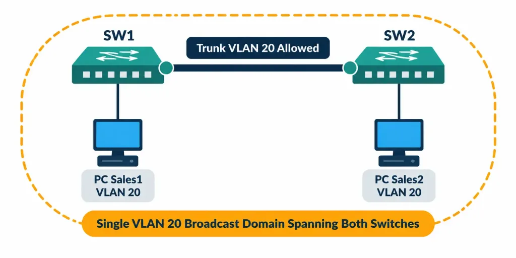
Real organizations rarely fit entirely within the port capacity of one physical switch. A Sales department might have people on the first floor of a building, connected to one switch, and additional Sales team members on the third floor, connected to a completely different physical switch elsewhere in the same building’s wiring closets. Both groups need to be in the same VLAN — the same broadcast domain, with unrestricted Layer 2 communication between them — despite being physically connected to entirely separate hardware.
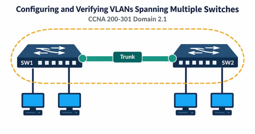
This is exactly the scenario spanning a VLAN across multiple switches solves. To make this work, the interconnecting link between the two switches must be configured as a trunk — a link specifically capable of carrying tagged traffic for multiple VLANs simultaneously across a single physical connection, rather than the single-VLAN-only behavior an access port provides. The full mechanics of trunking (802.1Q tagging, native VLAN behavior, and related configuration) are covered in complete depth in the next lesson; for this objective, the key conceptual point is narrower and more direct: spanning a VLAN across switches requires a trunk link between them, specifically configured to permit that VLAN’s traffic to cross it.
The Common Pitfall: Creating a VLAN Doesn’t Automatically Make It Reachable Elsewhere
This is worth its own dedicated section, since it’s precisely the mistake this objective’s own reference material calls out by name, and it’s a genuinely common real-world and exam-tested error.
Creating a VLAN on Switch A does absolutely nothing, by itself, to make that VLAN reachable or usable on Switch B. VLANs are, by default, local to the specific switch they’re configured on. For a VLAN to actually span multiple switches successfully, two separate conditions must both be satisfied simultaneously:
- The VLAN itself must exist on every switch along the path that traffic for it needs to traverse — not just the two switches with actual end devices connected, but any intermediate switch the trunk path happens to pass through as well.
- Every trunk link along that same path must be explicitly configured to permit that specific VLAN’s traffic to cross it — a trunk link, by default configuration in many cases, may not automatically carry every possible VLAN, and an administrator specifically needs to confirm the relevant VLAN is included in that trunk’s allowed list.
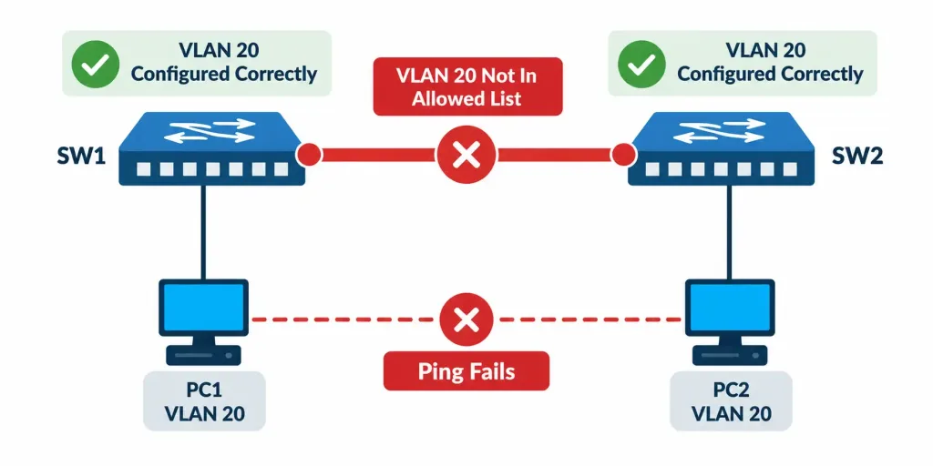
Worked example demonstrating exactly how this pitfall breaks connectivity in practice: an administrator creates VLAN 20 (Sales) on Switch A and assigns a port to it, then separately creates VLAN 20 on Switch B and assigns a different port to it there as well — reasonably assuming, at this point, that Sales devices on both switches can now communicate.
But if the trunk link connecting Switch A and Switch B was never specifically configured to allow VLAN 20’s traffic across it (perhaps it was configured to allow only VLANs 1 and 10, for entirely separate reasons unrelated to this new VLAN), Sales devices on the two switches remain completely unable to reach each other, despite both switches individually having a seemingly correct, complete VLAN 20 configuration in isolation. The VLAN existing correctly on both ends means nothing if the path connecting them doesn’t actually permit that VLAN’s traffic to cross it.
Why this specific failure mode is easy to miss during real troubleshooting: show vlan brief on either individual switch would show VLAN 20 as correctly configured and active, with its expected access port properly listed — nothing about that specific switch’s own local configuration looks wrong at all, because it genuinely isn’t wrong in isolation. The actual problem sits specifically on the trunk link’s allowed-VLAN configuration, a detail that requires checking the trunk itself directly (with show interfaces trunk, covered in full in the next lesson) rather than simply confirming each switch’s local VLAN database looks correct on its own.
A Brief Note on VTP (VLAN Trunking Protocol)
One way to avoid manually creating identical VLANs on every switch individually is VTP (VLAN Trunking Protocol), a Cisco-proprietary mechanism allowing switches to automatically synchronize their VLAN databases with each other across trunk links, so a VLAN created on one switch (configured as a VTP server) automatically propagates to other switches in the same VTP domain, without requiring the same manual vlan command to be repeated individually on every switch.
This is worth knowing exists, with an important, genuine caveat: VTP has real, well-documented operational risks if misconfigured — a switch introduced into an existing VTP domain with a higher revision number than the current configuration can inadvertently overwrite and delete existing VLANs across the entire domain, a genuinely disruptive real-world failure mode that has caused real outages in production networks.
Because of this risk, many current best-practice deployments deliberately use VTP transparent mode (where a switch forwards VTP advertisements without actually applying them to its own local VLAN database) or avoid VTP synchronization entirely, manually configuring VLANs on each switch individually instead — the explicit, manual approach this lesson’s core configuration example demonstrates. VTP’s full configuration and operational detail sits beyond this specific objective’s core scope, but recognizing it exists, understanding conceptually what problem it’s trying to solve, and being aware of its genuine misconfiguration risk are all worth carrying forward.
Configuring VLANs Spanning Two Switches: A Complete Walkthrough
Bringing every piece of this lesson together, here’s a complete, realistic configuration spanning VLAN 20 (Sales) across two switches connected by a trunk link.
Topology: SW1 and SW2 are connected via a trunk link on GigabitEthernet0/24 on both switches. SW1 has a Sales user connected to Gi0/1; SW2 has a second Sales user connected to Gi0/1 as well.
Configuring SW1:
SW1(config)# vlan 20
SW1(config-vlan)# name Sales
SW1(config-vlan)# exit
SW1(config)# interface GigabitEthernet0/1
SW1(config-if)# switchport mode access
SW1(config-if)# switchport access vlan 20
SW1(config-if)# exit
SW1(config)# interface GigabitEthernet0/24
SW1(config-if)# switchport mode trunk
SW1(config-if)# switchport trunk allowed vlan 20
Configuring SW2:
SW2(config)# vlan 20
SW2(config-vlan)# name Sales
SW2(config-vlan)# exit
SW2(config)# interface GigabitEthernet0/1
SW2(config-if)# switchport mode access
SW2(config-if)# switchport access vlan 20
SW2(config-if)# exit
SW2(config)# interface GigabitEthernet0/24
SW2(config-if)# switchport mode trunk
SW2(config-if)# switchport trunk allowed vlan 20
Notice precisely what had to be repeated on both switches, directly reflecting the common pitfall covered above: VLAN 20 was created independently on both SW1 and SW2 (satisfying condition one from the pitfall section), and the switchport trunk allowed vlan 20 command was applied on both ends of the trunk link (satisfying condition two). Skipping either of these steps on either switch would reproduce exactly the broken-but-looks-fine-in-isolation scenario described earlier.
Verifying the complete configuration:
SW1# show vlan brief

VLAN Name                             Status    Ports
---- -------------------------------- --------- -------------------------------
1    default                          active    Gi0/2, Gi0/3
20   Sales                            active    Gi0/1

SW1# show interfaces trunk

Port        Mode         Encapsulation  Status        Native vlan
Gi0/24      on           802.1q         trunking      1

Port        Vlans allowed on trunk
Gi0/24      20
The second command here, show interfaces trunk, is genuinely essential verification for this specific objective, even though full trunk configuration detail belongs to the next lesson — it directly confirms the trunk is active and, critically, that VLAN 20 specifically appears in the “Vlans allowed on trunk” list. Checking only show vlan brief on each switch individually, as noted in the pitfall discussion above, would miss this equally important second half of the verification picture entirely.
Packet Tracer Practice Activity: Spanning a VLAN Across Two Switches
Background/Scenario: Your company’s Sales department has team members on two different floors, each connected to a separate switch. Your task is to configure VLAN 20 (Sales) on both switches, connect them via a trunk, and verify that devices in Sales on both switches can communicate.
Topology (build this in Packet Tracer or GNS3):
[PC-Sales1]---[SW1]======Trunk Link======[SW2]---[PC-Sales2]Addressing table:
| Device | Interface | VLAN | IP Address |
|---|---|---|---|
| PC-Sales1 | NIC | 20 | 192.168.20.10/24 |
| PC-Sales2 | NIC | 20 | 192.168.20.11/24 |
Part 1: Configure basic device settings
- Configure a hostname on each switch matching the topology (SW1, SW2).
Part 2: Configure and verify VLANs
- Create VLAN 20, named Sales, on both SW1 and SW2.
- Assign the port connecting to PC-Sales1 on SW1 to VLAN 20 as an access port.
- Assign the port connecting to PC-Sales2 on SW2 to VLAN 20 as an access port.
- Configure the link between SW1 and SW2 as a trunk on both ends, explicitly permitting VLAN 20.
- Configure PC-Sales1 and PC-Sales2 with the IP addresses from the table above.
Verification steps — expected output when done correctly:
show vlan briefon both switches should show VLAN 20 (Sales) as active, with the correct access port listed on each.show interfaces trunkon both switches should show the interconnecting link as trunking, with VLAN 20 appearing in the allowed VLAN list.pingfrom PC-Sales1 to PC-Sales2 should succeed, confirming the VLAN successfully spans both switches.- As a deliberate troubleshooting exercise, try removing VLAN 20 from the trunk’s allowed list on one switch only, and observe that the ping between the two PCs now fails, despite both switches’ individual
show vlan briefoutput still looking entirely correct — directly reproducing the common pitfall covered earlier in this lesson.
You can build this same topology yourself in Packet Tracer or GNS3 to practice hands-on — deliberately breaking and then re-fixing the trunk’s allowed VLAN list is genuinely one of the most effective ways to internalize why this specific pitfall matters.
Common Misconceptions Worth Correcting Directly
“Creating a VLAN on one switch makes it available network-wide automatically.” As covered in detail above, this is precisely the core pitfall this objective tests — VLANs are local to each switch by default, and both the VLAN’s existence and the trunk’s allowed-VLAN configuration must be correctly set on every switch and link along the path for a VLAN to genuinely span multiple switches.
“Access ports and trunk ports are basically the same thing, just with different names.” They serve genuinely different purposes: an access port carries untagged traffic for exactly one VLAN, intended for connecting end devices that have no VLAN awareness at all; a trunk port carries tagged traffic for potentially many VLANs simultaneously, intended specifically for switch-to-switch (or switch-to-router) interconnections. Using the wrong type for a given connection produces genuinely broken behavior, not just a suboptimal but functional configuration.
“VLAN 1 is a safe, ordinary choice for production traffic like any other VLAN.” As covered above, VLAN 1’s status as the universal default (for both access ports and native VLAN behavior on trunks) makes it a predictable, less deliberately-secured choice in many real deployments — common practice actively avoids placing genuine production traffic on VLAN 1 specifically because of this default, unconfigured status, even though nothing technically prevents it from being used exactly like any other VLAN.
“VTP is always the right way to keep VLANs consistent across multiple switches.” As covered directly above, VTP carries a genuine, documented misconfiguration risk capable of causing real network outages, which is exactly why many current deployments deliberately avoid full VTP synchronization in favor of either VTP transparent mode or straightforward manual VLAN configuration on each switch — the same explicit approach demonstrated throughout this lesson’s own configuration examples.
Frequently Asked Questions
Can a single switch port belong to more than one VLAN simultaneously?
Not as a standard access port — an access port belongs to exactly one VLAN by definition. A trunk port, by contrast, is specifically designed to carry traffic for multiple VLANs simultaneously, which is the entire mechanism this lesson’s spanning scenario relies on.
What happens if I try to assign a port to a VLAN that hasn’t been created yet?
Depending on the specific IOS version, this typically either fails outright or automatically creates the VLAN using a default name — but relying on this automatic behavior isn’t good practice, since it bypasses the deliberate naming and planning a manually created VLAN typically involves, and behavior can vary between platforms.
Is there a limit to how many VLANs a switch can support?
Yes — the normal range covers VLAN IDs 1 through 1005, and the extended range covers 1006 through 4094, though actual practical limits also depend on the specific switch hardware’s own capacity, which can be considerably lower than the theoretical maximum ID range on lower-end platforms.
Do I need a router to span a VLAN across two switches, the way I would to route between two different VLANs?
No — spanning a single VLAN across multiple switches via trunking is a Layer 2 operation entirely, requiring no Layer 3 routing device at all. A router (or Layer 3 switch) only becomes necessary when traffic needs to cross between two genuinely different VLANs, which is a separate scenario from simply extending one VLAN’s reach across multiple switches.
Why did the Packet Tracer lab specifically ask me to remove a VLAN from the trunk’s allowed list as a deliberate exercise?
Because reading about a common pitfall and actually experiencing its specific, sometimes confusing symptom firsthand — a configuration that looks entirely correct on each individual switch, yet still fails to actually work — builds far more durable, transferable troubleshooting intuition than simply memorizing the pitfall’s description as an abstract fact to recall later.
VLAN Configuration, Trunking & VTP Quiz
Test your knowledge of VLANs, access ports, trunk links, VLAN IDs, VLAN 1, VTP, and common VLAN troubleshooting issues.
Summary
- A VLAN creates a logical, separate broadcast domain through configuration alone, with devices in different VLANs unable to communicate without Layer 3 routing between them.
- Basic VLAN configuration involves two steps: creating the VLAN, and separately assigning access ports to it, verified with show vlan brief.
- Spanning a VLAN across multiple switches requires a trunk link between them, and the VLAN must exist on every switch and be permitted on every trunk along the path.
- The most common pitfall is assuming a VLAN created on one switch automatically becomes reachable elsewhere — both the VLAN’s existence and the trunk’s allowed-VLAN configuration must be verified independently, since show vlan brief alone won’t reveal a trunk-side misconfiguration.
- show interfaces trunk is essential verification alongside show vlan brief, since it confirms which VLANs are actually permitted to cross a given trunk link.
- VTP can automate VLAN synchronization across switches but carries a genuine misconfiguration risk, which is why many deployments prefer manual configuration or VTP transparent mode instead.