Domain 4.6 | IP Services — 10% of exam
Learning Objectives
By the end of this lesson, you will be able to:
- Configure a router interface to operate as a DHCP client, obtaining its own addressing automatically.
- Explain the specific architectural problem DHCP relay solves, and why routers don’t forward broadcasts between subnets by default.
- Configure
ip helper-addresson a router interface to forward DHCP requests to a centralized server on a different subnet. - Identify which other UDP-based broadcast protocols
ip helper-addressforwards by default, beyond DHCP alone. - Verify DHCP client and relay operation using appropriate show and debug commands.
Key Terms Glossary
| Term | Definition |
|---|---|
| DHCP client | A device configured to request its own IP addressing information automatically, rather than using static configuration. |
| DHCP relay / IP helper | A router feature that converts a broadcast DHCP request into a unicast request forwarded to a specific server on another subnet. |
| Broadcast domain | The set of devices that receive a Layer 2 broadcast frame — routers do not forward broadcasts between separate broadcast domains by default. |
| Relay agent | The router (or Layer 3 switch) interface performing the broadcast-to-unicast conversion on behalf of clients. |
| ip helper-address | The interface configuration command enabling DHCP relay and specifying the destination server’s address. |
| Centralized DHCP deployment | A network design using one DHCP server to serve clients across many subnets or VLANs, rather than a separate server per subnet. |
DHCP Client Mode: Requesting, Not Providing
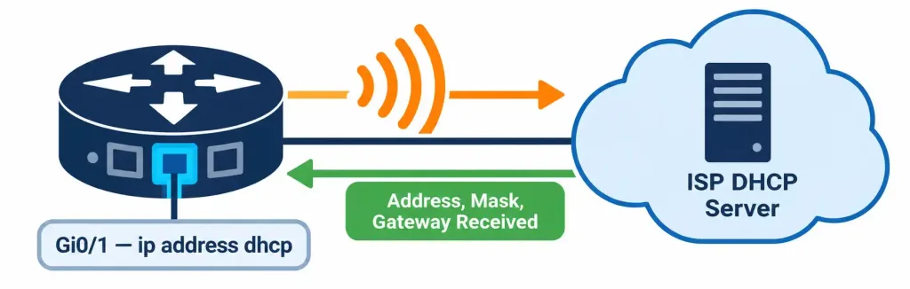
Objective 4.3 covered DHCP from the server’s perspective — the DORA process, and everything a DHCP server can hand out to a requesting client. This objective looks at the other side of that same exchange: a device configured as a DHCP client doesn’t wait to be manually assigned an address at all — it actively requests one automatically, running through the same Discover-Offer-Request-Acknowledge sequence as any other DHCP client, whether that device is a laptop, a phone, or a router interface itself.
Configuring a router interface as a DHCP client is common on an edge router’s outside-facing interface, particularly in small office or home office deployments where an ISP hands out an address dynamically rather than the customer having a static public address:
interface GigabitEthernet0/1
 ip address dhcp
This single line replaces a static ip address configuration entirely — the interface now runs the full DORA process itself at startup (and periodically thereafter, to renew its lease, exactly as described in objective 4.3) rather than using a fixed, manually typed address. Once the exchange completes, the interface holds whatever address, subnet mask, and default gateway the DHCP server provided, visible with a standard show ip interface brief or show interface command just like any statically configured interface.
The Problem DHCP Relay Solves
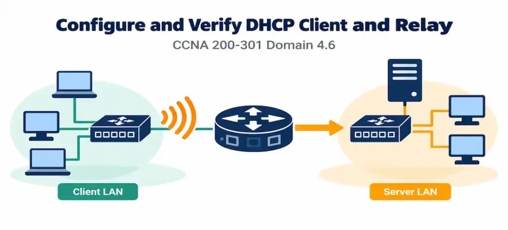
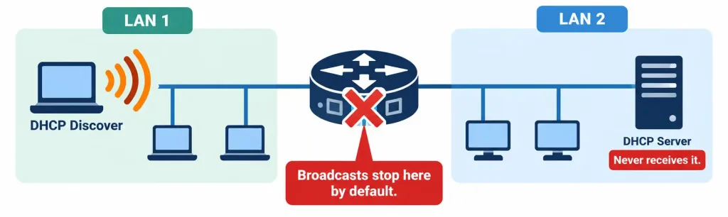
DHCP’s Discover message, as covered in objective 4.3, is a broadcast — the client has no IP address yet and no way to address a specific server directly, so it broadcasts to the entire local segment instead. This works perfectly when the DHCP server sits on the same subnet as the client. It breaks down entirely the moment the DHCP server sits on a different subnet, which is an extremely common real-world design: rather than deploying a separate DHCP server on every VLAN or subnet in an organization, most networks centralize DHCP on one server (or a small redundant pair) serving addressing needs across the entire organization.
The reason this breaks is fundamental to how routers operate: routers don’t forward broadcast traffic between subnets by default. A broadcast is, by definition, meant for the local segment only — forwarding every broadcast everywhere would flood the entire network with traffic that was never intended to leave its originating segment. This is correct, sensible default behavior for broadcasts in general, but it creates a specific problem for DHCP: a client’s broadcast Discover message never reaches a DHCP server sitting on a different subnet, no matter how well-routed the path between them otherwise is.
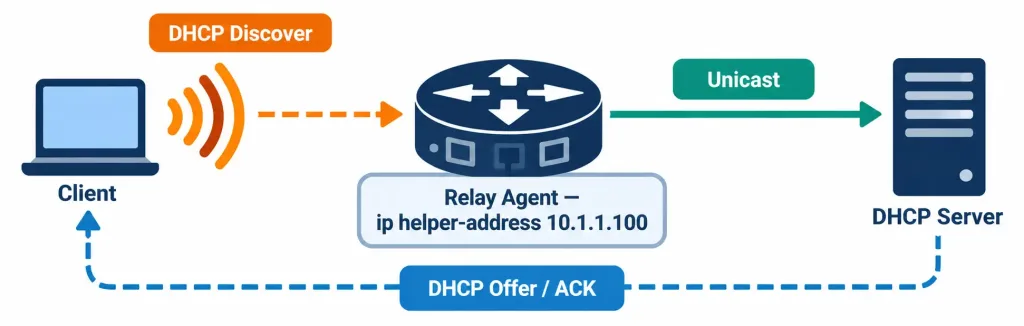
DHCP relay, configured with the ip helper-address command, solves this directly. Applied on the router interface facing the client subnet:
interface GigabitEthernet0/1
 ip helper-address 10.1.1.100
This tells the router: any DHCP broadcast received on this interface should be converted into a unicast packet and forwarded directly to 10.1.1.100, the centralized DHCP server’s address. The router — now acting as a relay agent — performs this conversion, and when the server’s response comes back, the relay agent forwards it back down to the originating client subnet, completing the exchange transparently from the client’s point of view. The client never knows its request took a detour through a unicast conversion process; it simply receives an offer and completes the DORA sequence normally.
What Else ip helper-address Forwards by Default
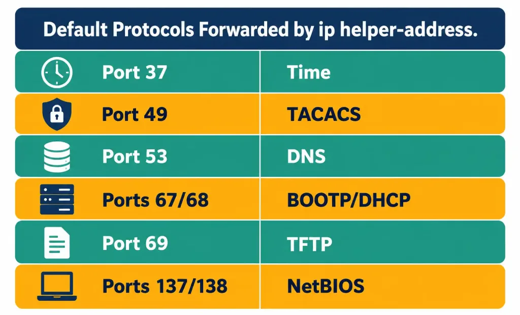
A detail worth knowing beyond the DHCP-specific framing: ip helper-address isn’t a DHCP-only feature — by default, it forwards a defined set of UDP-based broadcast protocols, not just DHCP’s ports (67 and 68). The default list includes:
| Port | Protocol |
|---|---|
| 37 | Time |
| 49 | TACACS |
| 53 | DNS |
| 67, 68 | BOOTP/DHCP |
| 69 | TFTP |
| 137, 138 | NetBIOS Name Service and Datagram Service |
This broader default exists because ip helper-address predates DHCP itself — it was originally designed for BOOTP, an older bootstrap protocol DHCP evolved from, and the command’s forwarding behavior was built to handle several common broadcast-based legacy services at once, not exclusively DHCP. In practice, most modern configurations care specifically about DHCP forwarding, but recognizing that a single ip helper-address command has this broader default scope is a useful detail — and one that can be narrowed with the no ip forward-protocol command if an administrator wants to exclude specific protocols from being relayed while keeping others active.
Redundancy with Multiple Helper Addresses
An interface isn’t limited to a single ip helper-address — multiple statements can be configured on the same interface, forwarding broadcast requests to more than one server simultaneously:
interface GigabitEthernet0/1
 ip helper-address 10.1.1.100
 ip helper-address 10.1.1.101
This provides redundancy: if the primary DHCP server is unreachable or fails to respond, the client’s broadcast has also been forwarded to a secondary server, which can respond in its place. Both servers receive the forwarded request; whichever responds first is generally the one whose offer the client accepts.
Common Misconceptions
- “
ip helper-addressonly works for DHCP.” By default, it forwards a broader set of UDP-based broadcast protocols (DNS, TFTP, NetBIOS, and others), not exclusively DHCP — DHCP is simply the most commonly relevant use case at the CCNA level. - “A router forwards broadcasts between subnets automatically once routing is configured.” Routing between subnets and forwarding broadcasts are entirely separate behaviors — a router will happily route unicast traffic between subnets while still never forwarding broadcast traffic between them without a specific mechanism like
ip helper-address. - “DHCP relay requires special configuration on the DHCP server itself.” The server doesn’t need to know anything special about relay — from its perspective, it simply receives what looks like a normal unicast DHCP request and responds accordingly; all the broadcast-to-unicast conversion work happens on the relay agent (router) interface.
- “A DHCP client interface configuration is only relevant for end-user devices, not routers.” Router interfaces, particularly edge/WAN-facing interfaces, are commonly configured as DHCP clients themselves, especially in small office/home office deployments where an ISP assigns addressing dynamically.
- “Multiple
ip helper-addressstatements on one interface cause a conflict.” They don’t — multiple statements simply forward the broadcast to multiple servers simultaneously, which is a deliberate and common redundancy design, not an error.
Configure and Verify: Full Lab Walkthrough
Topology: A central Layer 3 switch, CORE-SW1, routes between two VLANs — VLAN 10 (192.168.10.0/24) and VLAN 20 (192.168.20.0/24) — neither of which has a local DHCP server. A centralized DHCP server sits on a separate management subnet, 10.1.1.0/24, reachable at 10.1.1.100. CORE-SW1 also has a WAN-facing router, EDGE-RTR1, whose outside interface obtains its address via DHCP from the upstream ISP.
   VLAN 10 (192.168.10.0/24) --- [CORE-SW1 SVI: 192.168.10.1] ---+
                                                                   |
   VLAN 20 (192.168.20.0/24) --- [CORE-SW1 SVI: 192.168.20.1] ---+---> DHCP Server: 10.1.1.100
                                                                   |    (reachable via routed path)
   EDGE-RTR1 Gi0/1 (ip address dhcp) <--- ISP hands out address --+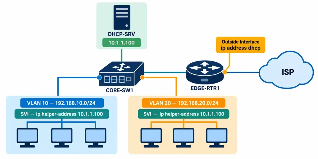
Step 1 — Configure ip helper-address on each VLAN’s SVI, pointing at the centralized DHCP server:
CORE-SW1(config)# interface Vlan10
CORE-SW1(config-if)# ip helper-address 10.1.1.100
CORE-SW1(config)# interface Vlan20
CORE-SW1(config-if)# ip helper-address 10.1.1.100
Each VLAN interface needs its own ip helper-address statement — relay configuration is applied per interface, on the interface facing the clients whose broadcasts need forwarding, not globally for the whole device.
Step 2 — Configure EDGE-RTR1’s outside interface as a DHCP client:
EDGE-RTR1(config)# interface GigabitEthernet0/1
EDGE-RTR1(config-if)# ip address dhcp
Step 3 — Verify a client on VLAN 10 successfully obtained an address from the centralized server. On the DHCP server itself (or via show ip dhcp binding if the server role lives on a Cisco device):
DHCP-SRV# show ip dhcp binding
IP address       Client-ID/Hardware address    Lease expiration       Type
192.168.10.20     0100.5056.9a3f.30             Sep 08 2026 04:02 PM   Automatic
192.168.20.15     0100.5056.9a3f.31             Sep 08 2026 04:05 PM   Automatic
Both bindings show addresses from the two separate client VLANs, despite the DHCP server itself living on an entirely different subnet — confirming the relay configuration successfully bridged both broadcast domains to the centralized server.
Step 4 — Verify the helper address configuration directly on CORE-SW1:
CORE-SW1# show ip interface Vlan10 | include Helper
  Helper address is 10.1.1.100
Step 5 — Verify EDGE-RTR1 successfully obtained its own address via DHCP client mode:
EDGE-RTR1# show ip interface brief
Interface              IP-Address      OK? Method Status                Protocol
GigabitEthernet0/1     203.0.113.45    YES DHCP   up                    up
The Method column showing DHCP (rather than manual, which would appear for a statically configured address) confirms this interface’s address came from a DHCP exchange rather than manual configuration.
Step 6 — For deeper troubleshooting, debug ip udp on the relay agent shows the actual broadcast-to-unicast conversion happening in real time (use cautiously on a production device, since debug output can be verbose):
CORE-SW1# debug ip udp
UDP: rcvd src=0.0.0.0(68), dst=255.255.255.255(67), length=300, input interface=Vlan10
UDP: sent src=192.168.10.1(67), dst=10.1.1.100(67), length=300, forwarded by ip helper
This confirms the exact behavior described conceptually earlier: a broadcast arriving on the client-facing interface is converted and forwarded as a unicast packet toward the configured helper address.
Packet Tracer Practice Activity
Scenario: Your organization is centralizing DHCP services on a single server rather than deploying one per VLAN. Configure relay on the appropriate router or Layer 3 switch interfaces so that clients on two separate VLANs can obtain addressing from the shared server, and configure a WAN interface to obtain its own address via DHCP from a simulated ISP.
Addressing table:
| Device | Interface | IP Address | Role |
|---|---|---|---|
| CORE-SW1 | VLAN 10 SVI | 192.168.10.1/24 | ip helper-address 10.1.1.100 |
| CORE-SW1 | VLAN 20 SVI | 192.168.20.1/24 | ip helper-address 10.1.1.100 |
| DHCP-SRV | NIC | 10.1.1.100/24 | Centralized DHCP server |
| EDGE-RTR1 | GigabitEthernet0/1 | Obtained via DHCP | Outside/WAN interface |
| PC1 | NIC (VLAN 10) | Obtained via DHCP | Client |
| PC2 | NIC (VLAN 20) | Obtained via DHCP | Client |
Part 1: Configure basic connectivity. Set up VLANs, SVIs, and routing so that 192.168.10.0/24, 192.168.20.0/24, and 10.1.1.0/24 can all reach each other, and confirm this with a ping between statically-addressed test interfaces before configuring any DHCP-related features.
Part 2: Configure DHCP relay. Apply ip helper-address 10.1.1.100 on both VLAN SVIs on CORE-SW1.
Part 3: Configure the DHCP server. Set up scopes on DHCP-SRV for both 192.168.10.0/24 and 192.168.20.0/24, each excluding its own gateway address and specifying the correct default gateway and DNS server options for that scope.
Part 4: Configure the WAN interface as a DHCP client. Apply ip address dhcp on EDGE-RTR1’s outside interface, assuming a simulated DHCP-capable ISP device is present in the topology.
Part 5: Verify. Confirm PC1 and PC2 each obtain an address on their correct respective subnet (not the DHCP server’s own subnet), confirm show ip dhcp binding on the server shows both, and confirm EDGE-RTR1’s outside interface shows DHCP as its addressing method in show ip interface brief.
Expected result: PC1 receives an address in 192.168.10.0/24, PC2 receives one in 192.168.20.0/24, both visible in the server’s binding table, and EDGE-RTR1’s WAN interface shows a DHCP-obtained address. If a client fails to obtain any address at all, check the relay configuration on that specific VLAN’s SVI first, since a missing or incorrect ip helper-address on just one interface will silently strand only that VLAN’s clients while the other VLAN continues working normally.
Troubleshooting Patterns
“Clients on one VLAN get addresses fine, but clients on another VLAN never do.” Check the ip helper-address configuration on that specific VLAN’s SVI — relay is configured per interface, so a single missing or mistyped statement isolates the problem to exactly the affected subnet while leaving everything else functioning normally.
“A client shows a 169.254.x.x self-assigned address despite relay being configured correctly.” Confirm basic routed reachability between the relay agent and the DHCP server itself — relay only works if the router can actually route the now-unicast packet to the server’s address; a routing problem between the two subnets produces exactly this symptom even with flawless helper address configuration.
“The DHCP server’s scope for a relayed subnet seems to be handing out the wrong gateway or DNS servers.” Confirm the server’s scope configuration for that specific subnet is correct — since a centralized server manages scopes for multiple subnets simultaneously, a misconfigured or overlapping scope definition for one subnet is a common, easy-to-miss mistake compared to a single-subnet deployment where there’s only one scope to get right.
“A router interface configured with ip address dhcp never obtains an address.” Confirm the upstream device (an ISP router, or in a lab, a simulated DHCP server on that segment) is actually reachable and configured to respond, and confirm nothing on that link is filtering DHCP’s broadcast or the eventual unicast renewal traffic.
“Multiple helper addresses are configured, but only one server ever seems to respond.” This is expected, not a fault — the client accepts whichever offer arrives first and simply ignores the other; both servers were still successfully reached, but only one “wins” the race under normal DORA behavior.
Frequently Asked Questions
Does ip helper-address need to be configured on the DHCP server’s own subnet interface?
No — it’s configured on the interface facing the client subnet that lacks a local DHCP server, not on the interface connected to the segment where the DHCP server itself resides.
Can a Layer 3 switch perform DHCP relay, or is it router-specific?
Any Layer 3-capable device with routed interfaces (a genuine router, or a multilayer switch with SVIs) can perform DHCP relay — the feature isn’t restricted to traditional routers specifically.
Is DHCP relay the same thing as DHCP itself running on a router?
No — a router can independently be configured as a DHCP server, a DHCP client, or a DHCP relay agent, and these are three distinct roles. This lesson’s relay discussion assumes the actual DHCP server role lives on a separate device from the relay agent.
What happens if the helper address points to an unreachable or nonexistent server?
The relay agent will still forward the request, but no response will ever come back, and clients on the affected segment will eventually fail to obtain an address and fall back to APIPA, exactly as if no DHCP server existed at all — the relay configuration itself doesn’t validate that the target server is actually alive.
Can ip helper-address forward traffic to a server on a completely different network, not just a nearby subnet?
Yes — as long as the relay agent has a valid route to the configured helper address, the server can be several hops away; relay doesn’t require the server to be on a directly connected subnet, only reachable via normal routing.
DHCP Client, Relay, and Helper Address: Practice Quiz
Test your knowledge of DHCP client configuration, relay agents, ip helper-address, and DHCP troubleshooting.
Summary
- A router interface configured with
ip address dhcpacts as a DHCP client, obtaining its own addressing automatically rather than through static configuration. - Routers don’t forward broadcast traffic between subnets by default, which breaks DHCP’s broadcast-based Discover message whenever the DHCP server sits on a different subnet than the client.
ip helper-address, configured on the interface facing the client subnet, converts DHCP broadcasts into unicast packets forwarded to a specific server, acting as a relay agent transparently to the client.- By default,
ip helper-addressalso forwards other UDP-based broadcast protocols (DNS, TFTP, NetBIOS, and others) — a legacy of the command originally supporting BOOTP before DHCP existed. - Multiple
ip helper-addressstatements on the same interface provide redundancy by forwarding to more than one DHCP server simultaneously. show ip interface brief,show ip interface <interface> | include Helper,show ip dhcp binding, anddebug ip udptogether confirm client, relay, and server-side behavior throughout the DHCP exchange.