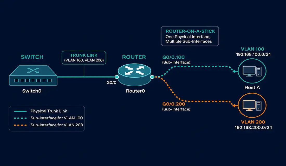
Legacy inter-VLAN routing needs one physical router interface for every VLAN. That works for a two- or three-VLAN network, but it runs out of interfaces fast. Router-on-a-stick solves this problem. It uses a single physical interface, split into multiple logical sub-interfaces, to route traffic for many VLANs at once.
This guide walks through the full lifecycle of a router-on-a-stick deployment. It covers how the design works, how to configure the switch and router, how to verify the setup with ping and traceroute, and how to troubleshoot the problems that come up most often in real networks and in VLAN trunking labs.
What Is Router-on-a-Stick Inter-VLAN Routing
Router-on-a-stick creates a virtual interface for each VLAN that needs routing. The router treats every VLAN-tagged frame as if it arrived on its own dedicated virtual interface, even though all of that traffic actually crosses one physical cable.
These virtual interfaces are called sub-interfaces. Each one is a software construct tied to a single physical interface. You configure a sub-interface in the router’s IOS with its own IP address and its own VLAN tag, so each sub-interface behaves like an independent, directly connected interface for its VLAN.
This design does not scale indefinitely. Router-on-a-stick does not scale beyond roughly 50 VLANs, a limit confirmed in Cisco’s own CCNA curriculum materials. Past that point, all inter-VLAN traffic is still forced through one trunk link, and the router itself runs into a practical ceiling on how many sub-interfaces it can manage efficiently. For networks with more VLANs than that, a Layer 3 (multilayer) switch using switched virtual interfaces is the standard alternative.
How Router-on-a-Stick Traffic Flows
Picture a simple two-VLAN topology: a switch with VLAN 100 and VLAN 200 configured, connected to a router over a single trunk link. The router’s physical interface has two sub-interfaces, one tagged for VLAN 100 and one tagged for VLAN 200.
Both sides of that single physical connection must be configured as an 802.1Q trunk: the switch port in trunk mode, and the router’s sub-interfaces each using encapsulation dot1q. That is what lets the router receive VLAN-tagged traffic from any VLAN on that one trunk and make a routing decision about where it goes next.
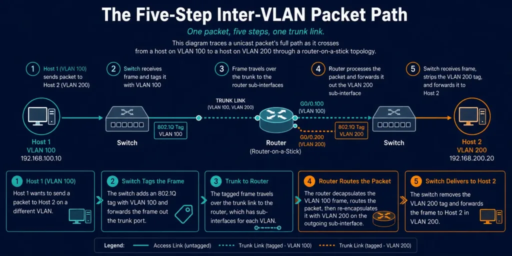
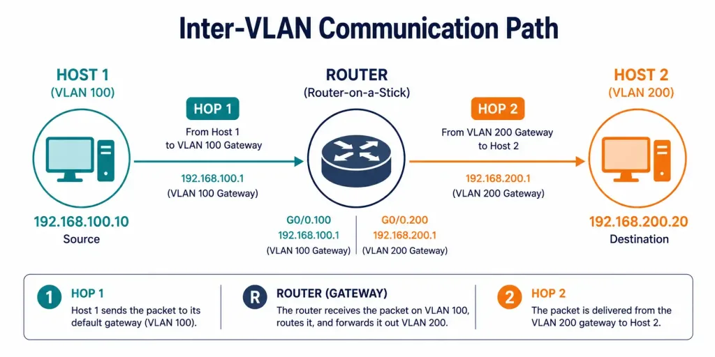
Here is the path a packet takes when Host 1 on VLAN 100 sends traffic to Host 2 on VLAN 200:
- Host 1 sends unicast traffic toward its default gateway.
- The switch tags that traffic as originating on VLAN 100 and forwards it out the trunk link toward the router.
- The router accepts the tagged frame on its VLAN 100 sub-interface. Because both sub-interfaces are directly connected to the router, it routes the packet from the VLAN 100 sub-interface to the VLAN 200 sub-interface.
- The router re-tags the outgoing frame as VLAN 200 and sends it back down the same trunk link to the switch.
- The switch strips the VLAN tag and forwards the untagged frame out the access port connected to Host 2.
The entire round trip uses exactly one physical link between the switch and the router. That is the whole point of the design.
Switch Configuration for Router-on-a-Stick
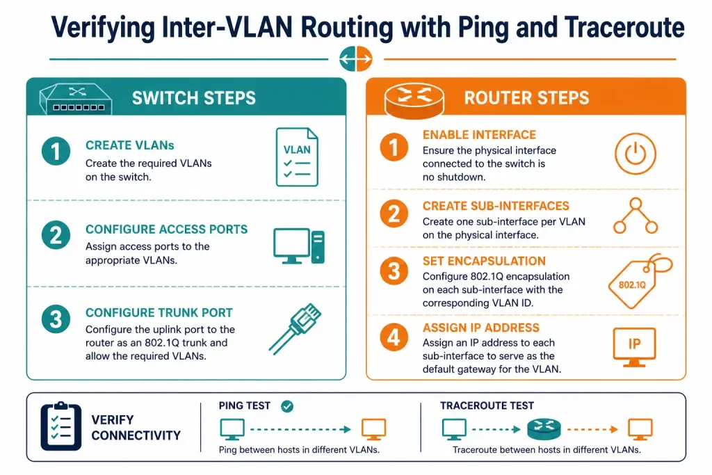
The switch side of the setup is straightforward: create the VLANs, assign host-facing ports to access mode, and configure the port connected to the router as a trunk.
Prerequisites
- VLANs 100 and 200 already exist on the switch.
- The switch port connecting to the router (for example, G0/1) is physically cabled and identified.
Configuration Steps
- Enter global configuration mode on the switch.
- Create the VLANs and give them descriptive names.
- Assign host-facing ports to access mode in their respective VLANs.
- Configure the router-facing port as an 802.1Q trunk.
- Save the configuration.
Example Configuration
Switch>enable
Switch#configure terminal
Switch(config)#vlan 100
Switch(config-vlan)#name admin
Switch(config-vlan)#exit
Switch(config)#vlan 200
Switch(config-vlan)#name account
Switch(config-vlan)#exit
Switch(config)#interface range gigabitEthernet 0/1 - 5
Switch(config-if-range)#switchport mode access
Switch(config-if-range)#switchport access vlan 100
Switch(config-if-range)#exit
Switch(config)#interface range gigabitEthernet 0/6 - 10
Switch(config-if-range)#switchport mode access
Switch(config-if-range)#switchport access vlan 200
Switch(config-if-range)#exit
Switch(config)#interface gigabitEthernet 0/1
Switch(config-if)#switchport mode trunk
Switch(config-if)#switchport trunk encapsulation dot1q
Switch(config-if)#exit
Switch(config)#do write
Building configuration...
[OK]
Switch(config)#exit
Verify the switch side with:
show vlan brief— confirms VLANs exist and lists which ports belong to each one.show interfaces trunk— confirms the trunk port is actually up and trunking, not sitting in access mode by default.
Router Configuration for Router-on-a-Stick
The router side creates one sub-interface per VLAN on the physical interface facing the switch.
Prerequisites
- The router’s physical interface (for example, G0/0) is cabled to the switch’s trunk port.
- The router’s IOS version supports 802.1Q sub-interfaces on that platform.
Configuration Steps
- Enter global configuration mode on the router.
- Bring up the physical interface with
no shutdown— sub-interfaces stay down if the parent interface is administratively down. - Create a sub-interface for each VLAN, set its 802.1Q encapsulation to match the VLAN ID, and assign it an IP address in that VLAN’s subnet.
- Save the configuration.
Example Configuration
Router>enable
Router#configure terminal
Router(config)#interface gigabitEthernet0/0
Router(config-if)#no shutdown
Router(config-if)#exit
Router(config)#interface gigabitEthernet0/0.100
Router(config-subif)#encapsulation dot1q 100
Router(config-subif)#ip address 192.168.100.1 255.255.255.0
Router(config-subif)#exit
Router(config)#interface gigabitEthernet0/0.200
Router(config-subif)#encapsulation dot1q 200
Router(config-subif)#ip address 192.168.200.1 255.255.255.0
Router(config-subif)#exit
Router(config)#do write
Building configuration...
[OK]
Router(config)#exit
Verify the router side with:
show ip interface brief— confirms each sub-interface has the correct IP address and shows as up/up.show running-config | section interface— confirms encapsulation and IP address per sub-interface.ping 192.168.200.2— confirms the router itself can reach a host across VLANs before you test end-to-end host connectivity.
Verifying Inter-VLAN Routing with Ping and Traceroute
Configuration alone does not prove the network works. Once the switch and router are configured, verify host-to-host connectivity with ping and traceroute.
Using Ping to Verify Inter-VLAN Routing
Ping sends an ICMP echo request to a destination address. When the destination receives it, it replies with an ICMP echo reply. The sending device times the gap between the request and the reply, and that gap is the connection’s latency.
A successful reply confirms two things at once: a working path exists between the source and destination, and the destination is actually up and processing traffic. In a router-on-a-stick lab, pinging Host 2 on VLAN 200 from Host 1 on VLAN 100 is the fastest way to confirm the whole chain — switch VLAN assignment, trunk, router sub-interfaces, and IP addressing — is working end to end.
Using Traceroute to Verify Inter-VLAN Routing
Traceroute (called traceroute on Unix-like systems, tracert on Windows) shows every hop between source and destination, not just whether the destination replied.
It works by manipulating the IP time-to-live (TTL) field. The first probe goes out with a TTL of 1, so it expires at the very first hop. That hop sends back an ICMP “time exceeded” message, which the source records as hop 1. The source then sends a probe with TTL 2, which expires at the second hop, and so on. The process repeats, incrementing the TTL each time, until a probe actually reaches the destination.
In the two-VLAN router-on-a-stick topology, a trace from a host on VLAN 100 to a host on VLAN 200 should show exactly two hops: the router’s VLAN 100 sub-interface (the source host’s default gateway) as hop 1, then the destination host as hop 2. If a trace shows more hops than expected, times out partway through, or never completes, that tells you exactly which segment of the path to investigate.
Troubleshooting Router-on-a-Stick and Inter-VLAN Routing
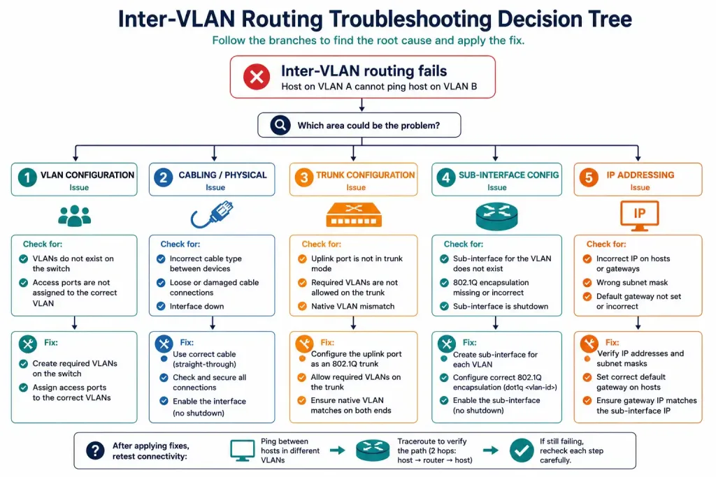
Most inter-VLAN routing failures trace back to one of five root causes: wrong VLAN on a switch port, a cable in the wrong port, a missing trunk, a sub-interface tagged for the wrong VLAN, or an IP addressing mistake. Each is straightforward to diagnose once you know where to look.
Switch Port Assigned to the Wrong VLAN
If a host’s access port is not in the VLAN you expect, that host’s traffic never reaches the router interface it needs. For example, if a host is wired into a port that’s part of VLAN 100 but the router link expects that VLAN on a different physical connection, the router simply has no path to forward the reply on, and communication silently fails in one direction.
Fix it by reassigning the access port to the correct VLAN:
Switch>enable
Switch#configure terminal
Switch(config)#interface FastEthernet 0/2
Switch(config-if)#switchport access vlan 100
Switch(config-if)#exit
Switch(config)#exit
Switch#write
Host or Router Cabled to the Wrong Port
A related but distinct problem: the VLANs and ports are configured correctly, but a cable is plugged into the wrong physical port. For example, a port assigned to VLAN 200 gets connected to a router interface configured for VLAN 100 instead of VLAN 200. Nothing about the configuration is wrong — the cabling just doesn’t match it. The fix here is physical: move the cable to the correct port. No further configuration changes are needed once the cabling is corrected.
Trunk Not Configured, or Trunk Down
In a router-on-a-stick topology specifically, the link between the switch and the router must be a trunk, not an access port. If that port is left in its default VLAN instead of trunk mode, the router’s sub-interfaces never see VLAN-tagged traffic at all, and inter-VLAN routing fails completely — not just for one VLAN, but for all of them, because they all depend on that single trunk.
Switch>enable
Switch#configure terminal
Switch(config)#interface G0/1
Switch(config-if)#switchport mode trunk
Switch(config-if)#exit
Switch(config)#exit
Switch#write
Even after a trunk is configured, it can still fail from a bad cable or a shut-down interface. If the trunk link goes down and there is no redundant path between the switch and router, every VLAN loses inter-VLAN connectivity at once — this is a strong signal to check show interfaces trunk and physical interface status first.
Verify trunk status with:
Switch#show interfaces trunk
Port        Mode         Encapsulation  Status
Gi0/1       trunk        802.1q         up
Sub-Interface Tagged for the Wrong VLAN
On the router side, the most common configuration mistake is a sub-interface with the wrong encapsulation dot1q VLAN ID, or an IP address that doesn’t match the VLAN it’s meant to serve. Check this with:
Router#show running-config | section interface
interface GigabitEthernet0/0.100
 encapsulation dot1q 100
 ip address 192.168.100.1 255.255.255.0
Compare the encapsulation VLAN ID against the IP subnet on that same sub-interface. If they don’t correspond to the same VLAN as configured on the switch, fix the encapsulation statement so the tag and the subnet agree.
show interfaces is also useful here for a lower-level view — it will show packet counters, encapsulation type, and interface resets for a specific sub-interface (for example, show interfaces fastEthernet 0/0.100), which helps confirm the interface is actually passing traffic and not just configured on paper.
IP Address and Subnet Mask Errors
Every VLAN needs its own unique subnet, and every device on that VLAN — the router’s sub-interface included — needs a correctly assigned IP address within that subnet. Two patterns cause most of the pain here:
- Wrong IP on the router interface or sub-interface. If the router’s address doesn’t match the subnet assigned to that VLAN, hosts on the VLAN can’t reach it as their gateway. Fix it with
ip address <ip-address> <subnet-mask>on the correct interface. - Wrong IP on a host. If a host’s static IP or DHCP-assigned address doesn’t fall within the VLAN’s subnet, it can’t reach the router either, even though the router itself is configured correctly.
Verifying IP and Subnet Configuration
show ip interface brief gives a quick per-interface summary of assigned IP addresses, which is usually the fastest way to spot a missing or mismatched address across every interface and sub-interface at once. show running-config confirms the same information alongside the rest of the interface configuration. On the host side, ipconfig /all (Windows) or the equivalent on other operating systems confirms what address, mask, and gateway the host itself believes it has — useful when the router side looks correct but the host still can’t connect.
Troubleshooting Reference Table
| Symptom | Likely Cause | Command to Check | Fix |
|---|---|---|---|
| One VLAN can’t reach the router | Access port in wrong VLAN | show interfaces switchport | switchport access vlan <id> |
| Devices in correct VLANs still can’t communicate | Cable in wrong port | show vlan brief, show interfaces trunk | Re-cable to correct port |
| All VLANs fail at once | Trunk not configured or down | show interfaces trunk | switchport mode trunk |
| One VLAN routes to the wrong subnet | Sub-interface VLAN ID/IP mismatch | show running-config | section interface | Correct encapsulation dot1q |
| Router unreachable from a VLAN | Wrong IP on router interface | show ip interface brief | ip address <ip> <mask> |
| One host unreachable, others fine | Wrong IP on that host | ipconfig /all | Correct host IP/mask/gateway |
Router-on-a-Stick vs. Multilayer Switch Routing
Router-on-a-stick is not the only way to do inter-VLAN routing, and it isn’t always the right one.
Router-on-a-Stick
- Pros: Uses a single router interface, cost-effective, works well for small to medium VLAN counts.
- Cons: All inter-VLAN traffic shares one trunk link, creating a potential bottleneck; does not scale beyond roughly 50 VLANs.
Multilayer Switch Routing
- Pros: Routing is done in hardware at wire speed, supports hundreds of VLANs, no single trunk bottleneck.
- Cons: Requires a Layer 3 switch, which costs more up front than adding sub-interfaces to an existing router.
Router-on-a-stick fits small networks, branch offices, and CCNA/CCNP lab environments well. For larger deployments or anywhere trunk-link congestion becomes a real concern, a multilayer switch with switched virtual interfaces is the standard production choice.
Example Topology
[See Topology Diagram: Two-VLAN Router-on-a-Stick Lab]
A minimal lab to practice everything above: one switch with VLAN 100 and VLAN 200, one host in each VLAN, and one router connected to the switch over a single trunk link with two sub-interfaces. Configure the switch and router as shown above, then verify with ping and traceroute between the two hosts. Once that works, deliberately break each of the five troubleshooting scenarios one at a time — wrong VLAN, wrong port, missing trunk, wrong sub-interface tag, wrong IP — and practice diagnosing each one using only the show commands listed in this guide.
Frequently Asked Questions
What is router-on-a-stick and how does it differ from legacy inter-VLAN routing?
Router-on-a-stick uses a single physical router interface, divided into multiple 802.1Q-tagged sub-interfaces, to route between VLANs. Legacy inter-VLAN routing instead requires a separate physical interface for every VLAN, which quickly exhausts the router’s available ports as a network grows. Router-on-a-stick removes that hardware constraint by handling the VLAN separation logically instead of physically.
How many VLANs can router-on-a-stick support?
Router-on-a-stick does not scale well beyond roughly 50 VLANs, a limit documented in Cisco’s own CCNA curriculum. Past that point, every VLAN still shares the same single trunk link, and the router accumulates enough sub-interfaces that management and performance both start to suffer. Networks with more VLANs than that typically move to a multilayer switch using switched virtual interfaces instead.
What are the basic steps to configure router-on-a-stick?
Configure the switch port connecting to the router as an 802.1Q trunk, then create a sub-interface on the router for each VLAN with the correct encapsulation VLAN ID and an IP address in that VLAN’s subnet. Make sure the router’s physical interface is enabled with no shutdown, since sub-interfaces stay down if the parent interface is administratively down. Save the configuration on both devices and verify with show ip interface brief and show interfaces trunk.
How do I verify that inter-VLAN routing is actually working?
Use ping between hosts on different VLANs to confirm basic reachability, and use traceroute to confirm the path takes the expected number of hops. In a simple two-VLAN topology, a trace between hosts should show exactly two hops: the source’s default gateway, then the destination. If ping fails or traceroute shows an unexpected hop count, that narrows down which segment of the path has a problem.
Why does inter-VLAN routing sometimes fail even after configuration looks correct?
The five most common causes are a switch port assigned to the wrong VLAN, a cable connected to the wrong physical port, a trunk link that was never enabled or has gone down, a router sub-interface tagged with the wrong VLAN ID, and an IP address or subnet mask mismatch somewhere in the chain. Working through show vlan brief, show interfaces trunk, show running-config, and show ip interface brief in that order will usually isolate which of the five is responsible.
Is router-on-a-stick suitable for large enterprise networks?
It’s generally not the right fit for large enterprise networks, mainly because of the roughly 50-VLAN scaling limit and the fact that every VLAN’s traffic funnels through a single trunk link. Multilayer switch routing, which performs Layer 3 routing in hardware and avoids the single-trunk bottleneck, is the more common choice at that scale. Router-on-a-stick remains a solid fit for smaller networks, branch sites, and certification labs where its simplicity and low cost outweigh its scaling limits.