Domain 2.0 | Network Implementation — 20% of exam
Learning Objectives
By the end of this lesson, you will be able to:
- Explain why devices on separate VLANs need a router to communicate, and why that traditionally required one physical interface per VLAN
- Define a subinterface and explain how it lets one physical interface service multiple VLANs
- Describe the router-on-a-stick design and the role of an 802.1Q trunk in making it work
- Read and interpret a subinterface configuration, including VLAN tagging and IP addressing
- Compare router-on-a-stick to Layer 3 switching as an inter-VLAN routing method
Key Terms
| Term | Definition |
|---|---|
| Subinterface | A logical division of a single physical interface, each configured with its own IP address and VLAN association |
| Router-on-a-Stick | A design where a single physical router interface, divided into subinterfaces, routes traffic between multiple VLANs over one trunk link |
| 802.1Q Trunk | A link that carries traffic for multiple VLANs, with each frame tagged to identify which VLAN it belongs to |
| Native VLAN | The one VLAN on an 802.1Q trunk whose traffic is sent untagged by default |
| Inter-VLAN Routing | The process of routing traffic between devices on different VLANs, which requires a Layer 3 device since VLANs are separate broadcast domains |
Explanation
Why Devices on Different VLANs Need a Router
This lesson previews a concept that Module 2’s switching lessons will cover in full: a VLAN groups switch ports into separate logical broadcast domains, even if they’re physically connected to the same switch. Two hosts on different VLANs are, from a Layer 2 perspective, on completely separate networks — a switch alone can’t move traffic between them. Something has to route between VLANs the same way it would route between any two separate networks, and that means a Layer 3 device has to get involved.
The most basic way to do this is to give the router one physical interface (and one cable) per VLAN, with each interface configured on that VLAN’s subnet. It works, but it doesn’t scale — a network with ten VLANs would need ten physical router interfaces and ten cables running to the switch, burning through router ports fast.
What a Subinterface Actually Is
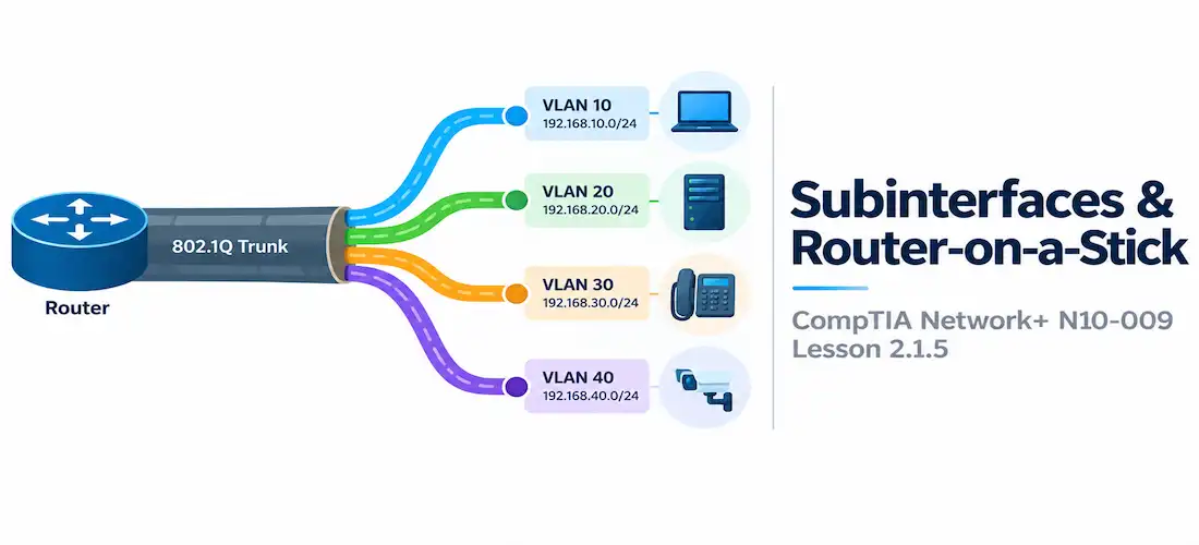
A subinterface solves the scaling problem by logically dividing one physical interface into multiple virtual interfaces, each with its own IP address and its own VLAN association. Instead of ten physical ports, a router can use a single physical interface — say GigabitEthernet0/0 — divided into GigabitEthernet0/0.10, GigabitEthernet0/0.20, GigabitEthernet0/0.30, and so on, one per VLAN.
This connects directly to the core infrastructure devices lesson from Module 1: a subinterface doesn’t change what a router does conceptually — it’s still routing between subnets — it just lets one physical port carry traffic for many logical networks at once.
The Router-on-a-Stick Design
Router-on-a-stick is the name for this whole design: one physical link (the “stick”) runs between the switch and the router, carrying traffic for every VLAN that needs inter-VLAN routing, and the router’s subinterfaces sort that traffic out on the other end.
For this to work, the single physical link has to be configured as an 802.1Q trunk on the switch side. A trunk tags each frame with a VLAN ID as it crosses the link, so that even though multiple VLANs share the same physical wire, the router (and the switch) always know which VLAN a given frame belongs to.
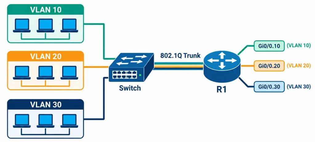
How A Single Trunk Link Lets One Router Interface Route Between Multiple VLANs
A basic router-on-a-stick configuration looks like this:
R1(config)# interface GigabitEthernet0/0.10
R1(config-subif)# encapsulation dot1Q 10
R1(config-subif)# ip address 192.168.10.1 255.255.255.0

R1(config)# interface GigabitEthernet0/0.20
R1(config-subif)# encapsulation dot1Q 20
R1(config-subif)# ip address 192.168.20.1 255.255.255.0
Each subinterface is bound to the physical interface (GigabitEthernet0/0) but behaves like an independent Layer 3 interface: it has its own subnet, its own IP address, and it participates in routing exactly as a separate physical interface would. The encapsulation dot1Q 10 line is what ties that specific subinterface to VLAN 10’s tagged traffic — without it, the subinterface has no way to know which frames on the shared physical link belong to it.
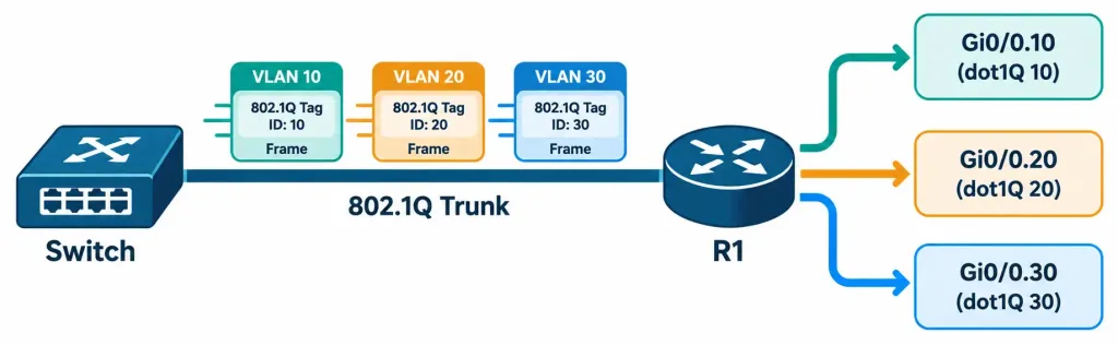
How Tagged Frames On The Trunk Are Sorted To The Matching Subinterface By VLAN ID
Native VLAN Considerations
On an 802.1Q trunk, exactly one VLAN is designated the native VLAN, and traffic for that VLAN is sent untagged by default — a legacy behavior from when trunking was first standardized, kept for backward compatibility with older equipment that doesn’t understand tags at all. If a subinterface is meant to handle the native VLAN, its configuration needs the encapsulation dot1Q <vlan> native keyword to tell the router to expect untagged frames for that specific VLAN.
A mismatched native VLAN — where the switch and router disagree on which VLAN is untagged — is a classic real-world (and exam) troubleshooting scenario: traffic on that VLAN either goes nowhere, or worse, leaks between VLANs in ways that are hard to spot without careful trunk verification.
Router-on-a-Stick vs. Layer 3 Switching
Router-on-a-stick isn’t the only way to route between VLANs, and it’s not always the best one. Many enterprise switches are Layer 3 switches, capable of doing inter-VLAN routing internally using switched virtual interfaces (SVIs) — a concept the next module section covers in depth. A Layer 3 switch skips the trunk-to-a-separate-router step entirely, routing between VLANs at wire speed inside the switch itself.
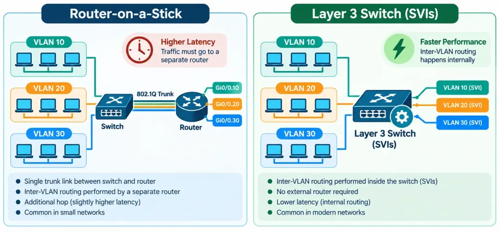
Comparing A Trunk-To-Router Design Against Inter-VLAN Routing Done Inside A Layer 3 Switch
Router-on-a-stick still shows up in smaller networks, lab environments, and situations where a dedicated router is already doing other jobs (like the NAT/PAT and dynamic routing work covered earlier in this module) and adding VLAN routing to it is more practical than provisioning a separate Layer 3 switch. But for anything beyond modest traffic volumes, a Layer 3 switch is generally the more scalable and lower-latency choice, since it avoids funneling every inter-VLAN packet down one shared physical link.
Where This Fits: Closing Out Objective 2.1
This lesson closes out N10-009 objective 2.1 (routing technologies). Across these five lessons, you’ve gone from static routes and route selection, through dynamic routing protocols, address translation, gateway redundancy, and now subinterfaces — the full set of tools a router uses to move traffic between networks. The next set of lessons shifts to objective 2.2, switching technologies, starting with VLANs themselves — the very concept this lesson had to introduce early, just to explain why subinterfaces exist in the first place.
Recognition-Level Verification Concepts
A few patterns are worth recognizing on sight:
- A physical interface name followed by a dot and a number (like
GigabitEthernet0/0.10) always indicates a subinterface. - An
encapsulation dot1Q <VLAN>line inside a subinterface configuration tells you exactly which VLAN that subinterface handles. - A single physical link carrying multiple VLANs, tagged per frame, is an 802.1Q trunk — the prerequisite for router-on-a-stick to function at all.
- The
nativekeyword appearing after a VLAN number in an encapsulation command flags that subinterface as handling untagged native VLAN traffic.
Common Exam Traps
- A subinterface is not a separate physical port. It’s a logical division of one physical interface — don’t confuse the two when reading a topology diagram or configuration.
- Router-on-a-stick requires the switch-side link to be a trunk, not an access port. Without 802.1Q trunking configured on the switch, VLAN tags never reach the router, and subinterfaces have nothing to sort.
- Native VLAN traffic is untagged by default — this is easy to forget and a common source of trunk mismatches when the switch and router disagree on which VLAN is native.
- Router-on-a-stick and Layer 3 switching solve the same problem differently. Don’t assume every inter-VLAN routing scenario uses subinterfaces — many modern designs use SVIs on a Layer 3 switch instead.
- Every subinterface needs its own
encapsulation dot1Qstatement. Forgetting it (or assigning the same VLAN number to two subinterfaces) is a frequent configuration mistake in this scenario.
Lesson 2.1.5 Practice Quiz — Subinterfaces and Router-on-a-Stick
17 questions covering subinterfaces, 802.1Q trunking, router-on-a-stick, native VLAN, and Layer 3 switching.
N10-009 · Domain 2.1Summary
Devices on different VLANs can't communicate without a Layer 3 device routing between them, since VLANs are separate broadcast domains.
A subinterface is a logical division of one physical interface, each with its own IP address and VLAN association, avoiding the need for one physical port per VLAN.
Router-on-a-stick uses a single 802.1Q trunk link between a switch and a router, with the router's subinterfaces sorting tagged frames by VLAN ID.
The native VLAN on a trunk is sent untagged by default, and a mismatch between switch and router native VLAN settings is a common troubleshooting scenario.
Layer 3 switches offer an alternative to router-on-a-stick, performing inter-VLAN routing internally via SVIs rather than funneling all traffic through one trunk to a separate router.
This lesson completes N10-009 objective 2.1 (routing technologies); the next lessons move into objective 2.2, switching technologies, starting with VLANs.