Domain 2.0 | Network Implementation — 20% of exam
Learning Objectives
By the end of this lesson, you will be able to:
- Explain the purpose and hierarchy of the MDF and IDFs in a structured cabling design
- Distinguish horizontal cabling from backbone (vertical) cabling and their distance limits
- Describe key rack considerations, including rack units and airflow management
- Explain the role of patch panels and cable management in a properly organized facility
- Recognize common rack and cabling installation mistakes
Key Terms
| Term | Definition |
|---|---|
| MDF (Main Distribution Frame) | The central facility where external service provider connections and internal backbone cabling converge |
| IDF (Intermediate Distribution Frame) | A satellite wiring closet, typically per floor or wing, connecting local work areas back to the MDF |
| Horizontal Cabling | Cabling running from an IDF to individual work area outlets, limited to a 90-meter permanent link under TIA/EIA-568 |
| Backbone (Vertical) Cabling | Cabling connecting an IDF back to the MDF, or MDF to MDF, often over longer distances than horizontal runs |
| Rack Unit (U) | A standardized measurement of rack-mount equipment height, equal to 1.75 inches |
Explanation
Shifting From Logical Design to Physical Installation
Every lesson in this module so far has been about logical configuration — routing tables, VLANs, wireless settings. This lesson and the next shift to something different: the physical facility that all of that logical configuration actually runs on top of. A perfectly configured network can still fail in practice if the physical cabling, racks, and facility design supporting it are done poorly.
MDF and IDF: The Backbone of Structured Cabling
In any building of meaningful size, network cabling follows a hierarchical structure built around two types of facilities:
The MDF (Main Distribution Frame) is the central point of the entire facility’s cabling design. This is typically where the internet service provider’s connection enters the building, and where the core network equipment — core routers and switches — physically lives.An IDF (Intermediate Distribution Frame) is a satellite wiring closet, usually placed on each floor or in each wing of a building, serving the local work area outlets in that section. Each IDF connects back to the MDF, rather than every single work area outlet in the building running all the way back to one central point.
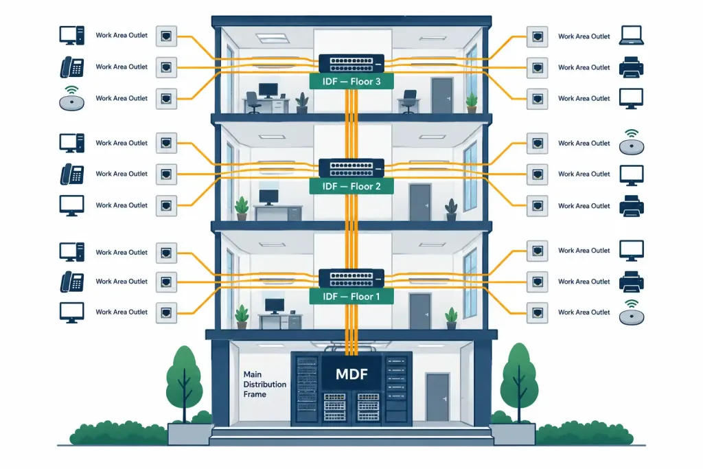
This hierarchical design exists for a practical reason: running individual cable from every desk in a large building directly to one central MDF would require enormous cable lengths, many of which would exceed usable distance limits entirely. Distributing that job across multiple IDFs keeps each cable run short and manageable.
Horizontal vs. Backbone Cabling
The cabling connecting these different points has two distinct names depending on what it connects:
Horizontal cabling runs from an IDF to the individual work area outlets it serves — the cable that ultimately reaches a desk, a wall jack, or an access point. The TIA/EIA-568 standard limits the permanent horizontal link to 90 meters, with an additional allowance for patch cords bringing the total channel length to 100 meters.
Backbone cabling (also called vertical cabling) connects an IDF back to the MDF, or connects multiple MDFs together across a campus. Because these runs are often longer — spanning multiple floors or even between buildings — backbone cabling frequently uses fiber optic cabling rather than copper, since fiber isn’t subject to the same 100-meter practical distance limitation that twisted-pair copper faces.Getting horizontal and backbone cabling mixed up is an easy mistake on the exam: horizontal cabling is about the “last stretch” to an individual outlet, while backbone cabling is about connecting distribution points to each other.
Rack Considerations
Network equipment in an MDF or IDF is almost always mounted in a rack, and a few rack-specific concepts come up constantly in real deployments:
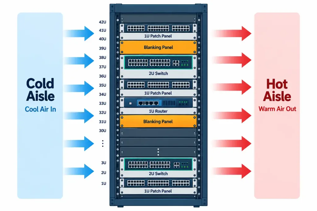
- Rack units (U) measure the height of rack-mounted equipment, with 1U equal to 1.75 inches. A device’s rack unit size directly determines how much vertical rack space it consumes — a “2U switch” takes up twice the vertical space of a “1U switch,” regardless of what’s actually inside it.
- Rack types vary by use case: two-post racks are lighter-duty and common for network equipment in smaller IDFs, while four-post racks (and full enclosed cabinets) provide more support and security for heavier equipment or environments needing physical access control.
- Airflow management matters more than it might seem. Equipment generates heat, and racks are typically arranged so that cold air is drawn in from one side (the “cold aisle”) and hot exhaust air is expelled out the other (the “hot aisle”). Blanking panels fill unused rack space to prevent hot exhaust air from recirculating back into the cold intake side, which would otherwise degrade cooling efficiency across the whole rack.
Patch Panels and Cable Management
A patch panel is where horizontal cabling from work area outlets physically terminates inside an IDF or MDF, providing a fixed, organized point that a short patch cord then connects to the actual switch port. This two-stage design — permanent cabling to the patch panel, then a flexible patch cord from the patch panel to the switch — means that changing which switch port a given outlet connects to only requires moving a short patch cord, not re-running the entire permanent cable run.
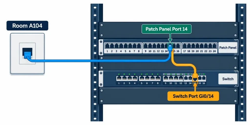
Good cable management goes beyond simply having a patch panel — properly routed and labeled cabling, cable management arms or rings to prevent strain and tangling, and clear labeling on both ends of every run all make a real difference when troubleshooting a problem months or years after installation. Poorly managed cabling — unlabeled, tangled, or improperly routed — turns a five-minute fix into a much longer troubleshooting exercise, since nobody can quickly tell which physical cable corresponds to which logical connection.
Recognition-Level Verification Concepts
A few patterns are worth recognizing on sight:
- A wiring closet on an upper floor connecting local work areas back to a central equipment room describes an IDF-to-MDF relationship.
- A cable run measured close to or exceeding 90 meters between an IDF and a wall outlet signals a horizontal cabling distance concern.
- Fiber optic cabling running between floors or buildings, rather than to individual desks, is almost always backbone (vertical) cabling.
- Unused rack space left without a blanking panel is a common airflow management oversight, even in an otherwise well-organized rack.
Common Exam Traps
- Horizontal cabling and backbone cabling are defined by what they connect, not by physical orientation alone. Horizontal cabling reaches individual work areas; backbone cabling connects distribution frames to each other — even though backbone cabling is often physically vertical between floors.
- The 90-meter horizontal cabling limit is for the permanent link, not the total channel. The 100-meter total includes patch cords at both ends — don’t confuse the two figures.
- A “2U” or “4U” measurement refers to rack space consumed, not processing power or port count. Don’t assume a larger rack unit size means a more capable device.
- Blanking panels are a real, tested airflow consideration, not a cosmetic detail — leaving rack space open without them allows hot and cold air to mix, reducing cooling efficiency.
- A patch panel is not the same thing as a switch. It’s a fixed termination point for permanent cabling; the actual switching happens on the separate device connected to it via patch cords.
Lesson 2.4.1 Practice Quiz — Rack, Cabling & Facility Considerations
17 questions covering MDF/IDF hierarchy, horizontal vs. backbone cabling, rack units, airflow, and patch panels.
N10-009 · Domain 2.4Summary
The MDF is the central point of a building's cabling design; IDFs are satellite closets on each floor or wing connecting back to the MDF, keeping individual cable runs manageable.
Horizontal cabling connects an IDF to individual work area outlets, limited to a 90-meter permanent link (100 meters total with patch cords); backbone cabling connects distribution frames to each other, often using fiber for longer runs.
Rack units (1U = 1.75 inches) measure equipment height, and proper airflow management — including blanking panels for unused space — keeps rack-mounted equipment cooled effectively.
Patch panels provide a fixed termination point for permanent cabling, letting a short patch cord handle the flexible connection to a switch port without disturbing the permanent cable run.
Good cable management and labeling save significant troubleshooting time later, while poor cable management turns simple fixes into extended, confusing exercises.