Domain 1.0 | Networking Concepts — 23% of exam
Learning Objectives
By the end of this lesson, you will be able to:
- Describe the primary function of a router and explain why it makes forwarding decisions differently than a switch
- Describe the primary function of a switch, including how it builds and uses a MAC address table
- Explain the role of a wireless access point (AP) in bridging wireless clients onto a wired network
- Explain why large wireless deployments use a wireless LAN controller (WLC) rather than managing each access point individually
- Compare these four core infrastructure devices side by side in terms of OSI layer, forwarding logic, and typical placement in a network
Key Terms
| Term | Definition |
|---|---|
| Router | A Layer 3 device that forwards packets between different networks based on destination IP address, using a routing table |
| Switch | A Layer 2 device that forwards frames between devices on the same network based on destination MAC address, using a MAC address table |
| Access Point (AP) | A device that provides a wireless (802.11) connection point for client devices and bridges that wireless traffic onto the wired network |
| Wireless LAN Controller (WLC) | A centralized device or software service that manages, configures, and monitors multiple lightweight access points from a single console |
| Autonomous AP | A standalone access point that handles its own management, configuration, and RF functions independently, with no controller |
| Lightweight AP (LWAP) | An access point that depends on a wireless LAN controller for its configuration, management, and much of its control-plane processing |
| CAPWAP | Control and Provisioning of Wireless Access Points — the tunneling protocol used between a lightweight AP and its WLC |
| MAC Address Table | A table a switch maintains, mapping MAC addresses to the physical ports through which those addresses were learned |
| Routing Table | A table a router maintains, listing known destination networks and the next-hop/interface used to reach them |
| Broadcast Domain | The set of devices that receive a broadcast frame sent by any member of that same set — bounded by routers, not by switches |
| Collision Domain | The set of devices that could cause a data collision if they transmitted at the same time — each switch port is its own collision domain on modern full-duplex networks |
| PoE (Power over Ethernet) | A technology that delivers electrical power to devices (such as APs) over the same Ethernet cable used for data |
Explanation
The Building Blocks of Every Network
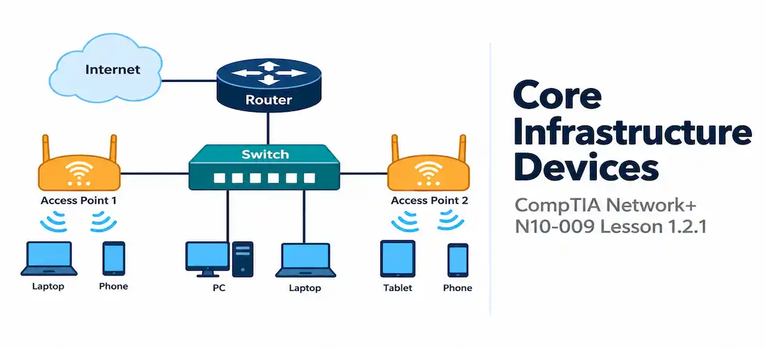
Whatever else a network does — carry voice traffic, host a data center application, connect a coffee shop’s guest Wi-Fi — it is built from a small set of core infrastructure devices performing a handful of well-defined jobs. Domain 1.2 of the Network+ exam asks you to recognize these devices, understand what layer of the OSI model they primarily operate at, and describe the specific job each one does.
This lesson covers four of the most fundamental: the router, the switch, the access point, and the wireless LAN controller. Later lessons in this module cover security appliances (1.2.2), traffic management appliances (1.2.3), and storage appliances (1.2.4) — this lesson focuses specifically on the devices that make basic connectivity and forwarding possible in the first place.
Understanding these devices is not just definitional trivia. Nearly every troubleshooting scenario on the exam, and in real jobs, starts with the question “which device is responsible for this behavior?” A misconfigured switch port produces different symptoms than a misconfigured router interface, and a coverage dead zone in a warehouse is a wireless infrastructure problem, not a switching problem. Knowing what each device does — and does not do — is foundational to isolating problems correctly.
Routers: Connecting Different Networks
A router is a Layer 3 device whose core job is to move packets between different networks. When a router receives a packet, it examines the destination IP address in the packet’s header, consults its routing table to determine the best next hop toward that destination network, and forwards the packet out the appropriate interface. This process, called routing, repeats at every router along the path until the packet reaches a router directly connected to the destination network.
Routers build their routing tables in one of two ways (covered in depth in Lesson 2.1.1): statically, where an administrator manually enters routes, or dynamically, where routing protocols such as OSPF, EIGRP, or BGP automatically discover and exchange route information with neighboring routers. Either way, the router’s essential job stays the same — find the best path to a destination network and forward accordingly.
A few characteristics define routers on the exam:
- They separate broadcast domains. A broadcast sent on one side of a router never crosses to the other side. This is a critical distinction from switches, which do not separate broadcast domains.
- Each interface typically sits on a different IP subnet. A router’s interface is the default gateway for the devices on its connected network segment.
- They can perform additional functions beyond pure forwarding, including Network Address Translation (NAT), access control (ACLs), and, on many small-office/home-office (SOHO) models, built-in switch ports and wireless radios — blurring the line between “router” and “all-in-one gateway device” in consumer contexts. On the exam, focus on the routing function itself as the defining characteristic, regardless of what else a given piece of hardware might also do.

Switches: Connecting Devices Within a Network
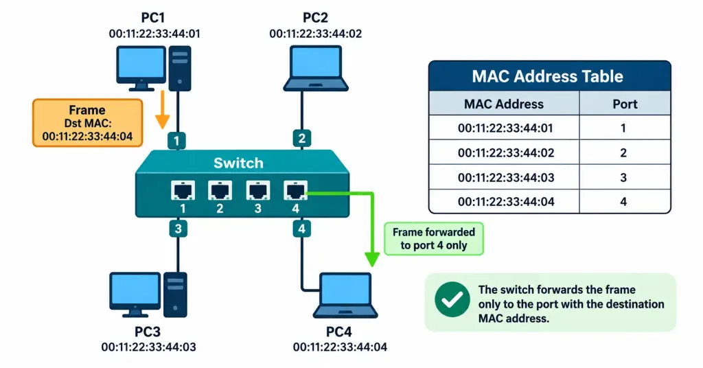
A switch is a Layer 2 device whose job is to forward frames between devices on the same network (the same broadcast domain), using physical (MAC) addressing rather than logical (IP) addressing. When a frame arrives on a switch port, the switch examines the frame’s destination MAC address and checks its MAC address table — a dynamically built list mapping MAC addresses to the ports on which those addresses were learned.
- If the destination MAC address is in the table, the switch forwards the frame only out the corresponding port — a much more efficient behavior than blindly repeating traffic to every port (which is what an old-style hub, a Layer 1 device, would do).
- If the destination MAC address is not yet in the table, the switch floods the frame out every port except the one it arrived on, and learns the actual location once a reply comes back.
- The switch continuously learns new MAC-to-port mappings by inspecting the source MAC address of every incoming frame, and it ages out entries it hasn’t seen traffic from recently (keeping the table current as devices move or disconnect).
Unlike routers, switches do not separate broadcast domains by default — every device connected to the same switch (or set of interconnected switches) is in the same broadcast domain unless VLANs are configured to logically segment it (VLANs are covered fully in Lesson 2.2.1). Switches do, however, separate collision domains: on modern full-duplex Ethernet, each switch port is its own collision domain, which is why collisions are effectively a non-issue on switched networks compared to old shared-media hub-based networks.
Switches come in a few practically important varieties for the exam:
- Unmanaged switches — plug-and-play devices with no configuration interface; common in very small or home networks.
- Managed switches — support configuration of VLANs, port security, link aggregation, and monitoring (SNMP); standard in business and enterprise environments.
- PoE switches — supply Power over Ethernet to connected devices (access points, IP phones, security cameras) over the same cable that carries data, eliminating the need for separate electrical wiring at the device.
Access Points: Bridging Wireless Clients to the Wired Network
An access point (AP) provides the connection point that lets 802.11 (Wi-Fi) wireless client devices join a network that is otherwise built on wired Ethernet infrastructure. Functionally, an AP acts as a Layer 2 bridge: it receives 802.11 frames from wireless clients over the air, translates them into standard Ethernet frames, and forwards them onto the wired switch it’s connected to — and performs the reverse translation for traffic heading back out to wireless clients.
APs come in two broad architectural models, and distinguishing between them is a frequently tested concept:
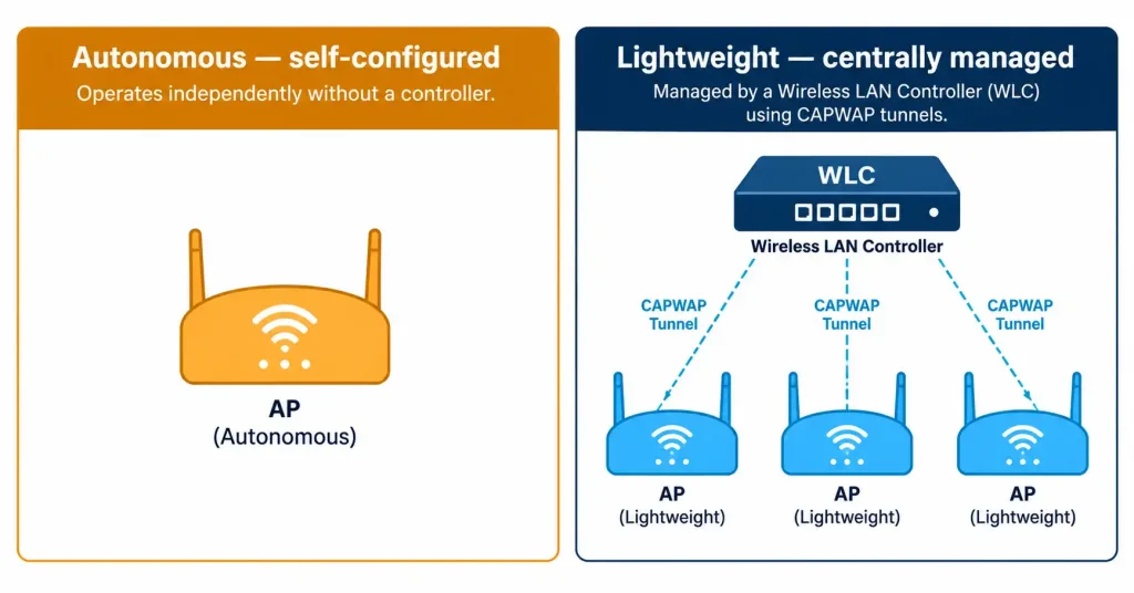
- Autonomous APs are fully self-contained. Each AP has its own configuration, manages its own radio settings (channel, power level, SSID broadcast), and operates independently of any other AP. This model is simple and doesn’t require additional infrastructure, but it does not scale well — administrators must log into and configure every single AP individually, and coordinating channel/power settings across dozens or hundreds of APs by hand becomes unmanageable.
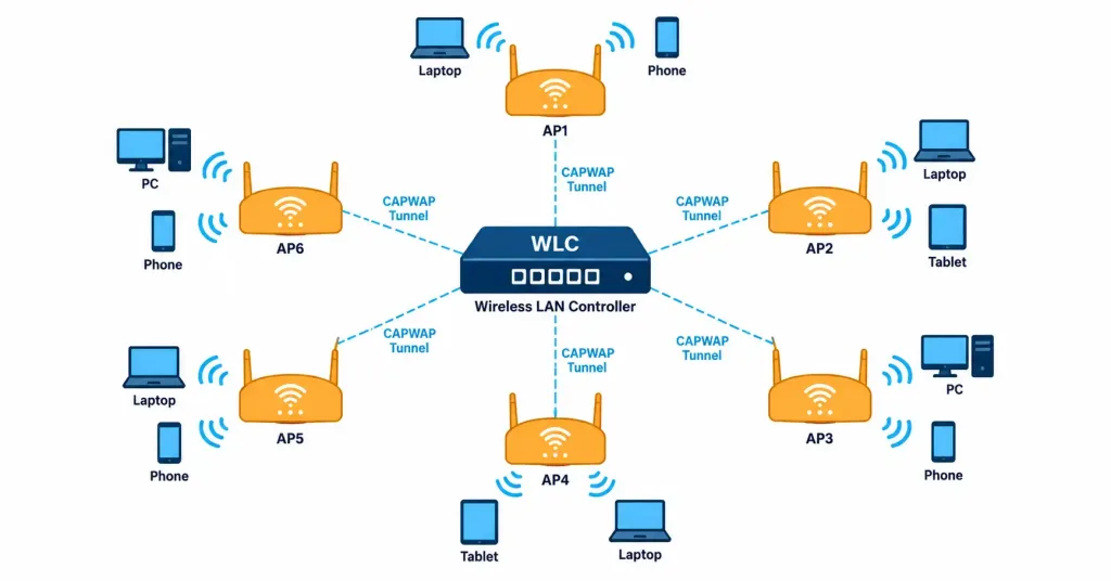
- Lightweight APs (LWAPs) offload their configuration and much of their control-plane logic to a centralized wireless LAN controller. A lightweight AP is, by itself, a comparatively “dumb” radio endpoint — it tunnels management and (often) data traffic back to the WLC using CAPWAP, and receives its channel assignments, power levels, SSIDs, and security policy from that controller.
Wireless LAN Controllers: Centralized Management at Scale
A wireless LAN controller (WLC) is the centralized brain behind a lightweight AP deployment. Rather than configuring each AP one at a time, an administrator configures the WLC once, and the WLC pushes consistent settings — SSIDs, security policies (WPA2/WPA3, RADIUS integration), channel plans, transmit power levels — out to every AP it manages.
Beyond basic configuration distribution, WLCs provide capabilities that are difficult or impossible to achieve with purely autonomous APs:
- Dynamic RF management — automatically adjusting channel assignments and transmit power across the entire AP fleet to minimize co-channel interference as conditions change (covered further in Lesson 2.3.1).
- Seamless roaming — allowing a wireless client to move between APs managed by the same controller without dropping its connection or being forced to re-authenticate from scratch.
- Centralized monitoring and troubleshooting — a single dashboard showing the health, client counts, and interference levels across every AP in the deployment, instead of needing to check dozens of individual AP web interfaces.
- Consistent security policy enforcement — ensuring every AP in the organization enforces the same authentication and encryption standards, rather than relying on each AP being configured correctly by hand.
The trade-off is that a WLC introduces a centralized point that must be sized, licensed (many enterprise WLCs are licensed per number of managed APs), and protected — if the WLC becomes unreachable, depending on the vendor and deployment mode, lightweight APs may lose the ability to accept new client connections or apply configuration changes until connectivity to the controller is restored. This is precisely why small deployments (a single office, a small retail location) often use a handful of autonomous APs instead — the operational overhead of a controller isn’t justified at that scale, while a multi-building campus or a chain of retail stores gains enormous administrative efficiency from centralizing control through a WLC.
Side-by-Side Comparison
| Device | Primary OSI Layer | Forwards Based On | Separates Broadcast Domains? | Typical Placement |
|---|---|---|---|---|
| Router | Network (Layer 3) | Destination IP address / routing table | Yes | Network edge; boundary between different networks |
| Switch | Data Link (Layer 2) | Destination MAC address / MAC table | No (unless VLANs are configured) | Access and distribution layers, connecting end devices |
| Access Point | Data Link (Layer 2), bridging function | 802.11 frame ↔ Ethernet frame translation | No | Wherever wireless coverage is needed, connected to a switch port |
| Wireless LAN Controller | Management/control plane (not a forwarding device in the traditional sense) | N/A — manages APs rather than forwarding user traffic itself | N/A | Centralized location (data center or cloud), reachable by all managed APs |
[See Diagram: Core Infrastructure Devices Compared — Layer, Forwarding Logic, and Placement]
How These Devices Fit Together in a Real Network
Picture a small business with a wired office area and a warehouse that needs Wi-Fi coverage. A router sits at the network edge, connecting the business’s internal network to its ISP and to any other remote sites. Behind the router, one or more switches interconnect desktops, printers, and IP phones, forwarding traffic between them based on MAC address without needing to involve the router at all — traffic only needs to reach the router when it’s headed to a different network (such as the Internet, or a separate VLAN). I
n the warehouse, several access points are mounted to provide wireless coverage; because there are enough APs to make centralized configuration worthwhile, they operate as lightweight APs, all managed by a single wireless LAN controller sitting in the office’s server rack (or hosted in the cloud). The switches also happen to supply PoE to the access points, so no separate electrical wiring had to be run to each AP’s mounting location.
This basic pattern — router at the edge, switches distributing connectivity, APs (optionally WLC-managed) extending that connectivity wirelessly — recurs at every scale, from a single retail location to a global enterprise with a spine-leaf data center core. Later lessons build directly on this foundation: Lesson 1.6.2 formalizes the layered architecture (access/distribution/core, spine-leaf) that these devices are typically arranged into, and Lesson 2.3.1 goes deeper into how wireless channel and band planning work once APs are deployed.
Recognition-Level Verification Concepts
This objective is descriptive/comparative rather than hands-on, so there’s no vendor-specific configuration to memorize here — that begins in Domain 2. It is worth recognizing, at a conceptual level, the kind of information each device type would show you if you were verifying its operation:
- On a switch, a command showing the MAC address table (vendor syntax varies, but conceptually a “show mac table” style command) reveals which MAC addresses are associated with which ports.
- On a router, a command showing the routing table reveals which networks the router knows how to reach and through which interface/next hop.
- On a wireless LAN controller, a dashboard or command-line view typically shows every AP it’s managing, each AP’s status, and the clients currently associated with each one.
You’ll build directly on this recognition-level understanding once you reach Domain 5’s troubleshooting content, where you’ll interpret actual command output to diagnose problems.
Common Exam Traps
- Don’t assume “router” and “Layer 3” are only about big enterprise gear. A home internet gateway is, functionally, a router (plus usually a switch, AP, and firewall all built into one box) — the exam tests the function, not the marketing name on the device.
- Switches do not stop broadcasts; routers do. This is one of the most reliably tested distinctions in this entire lesson — do not mix it up.
- Autonomous vs. lightweight is about where configuration and control-plane intelligence live, not about whether the AP is “better” — lightweight APs depend on a WLC; autonomous APs don’t need one.
- A WLC does not typically forward user data traffic itself in most deployment modes — its job is centralized management, configuration distribution, and control functions for the APs, not acting as a switch or router for client traffic (though some deployment modes do tunnel client data through the controller — know that this varies by vendor and configuration, and the exam tests the concept of centralized management as the defining characteristic).
- PoE is a power delivery method, not a device category — don’t confuse a “PoE switch” with a separate class of device; it’s simply a switch with the added capability of delivering power over its Ethernet ports.
Lesson 1.2.1 Practice Questions
Core Infrastructure Devices · 17 questions · Network+ N10-009, Domain 1.0
Which device makes forwarding decisions based on destination IP address and a routing table?
What does a switch use to determine which port to forward a frame out of?
A junior technician insists that a switch could route traffic between two different IP subnets if its MAC address table were just large enough. Which statement corrects this misunderstanding?
Which two of the following are true about a lightweight access point (LWAP)?
A coffee shop owner installs a single access point for guest Wi-Fi. There is no separate management appliance anywhere on the network, and all wireless settings are configured by logging directly into the AP's own web interface. What type of AP is this?
A frame destined for MAC address 0011.2233.4455 arrives on interface Gi0/7. Based on the output below, what will SW1 do?
Which of the following best describes the primary advantage of using a wireless LAN controller (WLC) in a deployment with 40 access points?
Which two of the following are functions typically associated with a router rather than a switch?
An administrator notices that a broadcast sent by a device on one switch reaches every other device connected to that same switch, but does not reach devices on the other side of the network's edge device. Which device is most likely responsible for stopping the broadcast?
What is the purpose of PoE (Power over Ethernet) in a network that includes several access points?
A new employee unboxes a small switch, plugs it in, connects a few devices, and finds no way to log in or configure it — it simply works immediately with default behavior. What kind of switch is this?
The diagram below shows several access points, all connected to switches, all tunneling control traffic to a single centralized device. What is that centralized device?

A frame arrives on a switch destined for a MAC address the switch has never seen before — there is no matching entry anywhere in its MAC address table. What does the switch do with this frame?
A network engineer is designing a wireless deployment for a five-building corporate campus with over 200 access points. Which architecture would provide the most efficient management?
Which two of the following are true about collision domains on a modern switched network?
What is the primary role of an access point in a wireless network?
Which type of device most likely produced the output below, and what is it doing with this information?
show ip route output — connected networks and a static default route toward a next-hop IP — is characteristic of a router, which uses this table to determine the best path toward each known destination network.Summary
Routers operate at Layer 3, forwarding packets between different networks based on destination IP address and a routing table, and they separate broadcast domains
Switches operate at Layer 2, forwarding frames within a network based on destination MAC address and a dynamically learned MAC address table; they separate collision domains but not broadcast domains (without VLANs)
Access points bridge wireless (802.11) client traffic onto the wired network, and come in two architectural flavors: autonomous (self-contained) and lightweight (dependent on a controller)
Wireless LAN controllers centralize configuration, RF management, and monitoring for large deployments of lightweight APs, communicating with them via CAPWAP
These four devices combine in predictable patterns — router at the edge, switches distributing wired connectivity, APs (optionally WLC-managed) extending that connectivity wirelessly — that recur at every scale of network design