Domain 1.0 | Networking Concepts — 23% of exam
Learning Objectives
By the end of this lesson, you will be able to:
- Compare the common twisted-pair copper cabling categories and their maximum supported speeds and distances
- Distinguish UTP from STP cabling and explain when shielding matters
- Compare single-mode and multi-mode fiber in terms of core size, light source, distance, and typical use case
- Identify common fiber connector types by shape and typical application
- Explain the trade-offs that lead an organization to choose copper versus fiber for a given link
Key Terms
| Term | Definition |
|---|---|
| UTP (Unshielded Twisted Pair) | Copper cabling using twisted wire pairs with no additional shielding, the most common cabling type in ordinary office environments |
| STP (Shielded Twisted Pair) | Copper cabling with additional shielding around the twisted pairs, reducing electromagnetic interference (EMI) at higher cost and reduced flexibility |
| Coaxial Cable | A cable with a central copper conductor surrounded by insulation, a metallic shield, and an outer jacket, historically used for cable television and broadband internet |
| Single-Mode Fiber (SMF) | Fiber optic cabling with a very small core that carries a single light path, typically using a laser light source, supporting the longest distances |
| Multi-Mode Fiber (MMF) | Fiber optic cabling with a larger core that carries multiple light paths simultaneously, typically using an LED or VCSEL light source, supporting shorter distances at lower cost than single-mode |
| Attenuation | The gradual loss of signal strength as it travels over a distance through a cable, affecting both copper and fiber, but through different underlying causes |
| Crosstalk | Interference caused by signals on one wire pair inducing an unwanted signal on an adjacent wire pair, relevant specifically to copper cabling |
Explanation
Cabling as the Physical Foundation
Every network, regardless of how sophisticated its logical design, ultimately depends on a physical medium to carry signals between devices — the OSI Physical layer (Layer 1) introduced back in Lesson 1.1. This lesson covers the two dominant physical cabling technologies Network+ expects you to know: copper (twisted-pair and coaxial) and fiber optic cabling, along with the standards, categories, and connector types associated with each. Wireless media and the transceivers that connect fiber/copper to networking equipment are covered separately in the next lesson (1.5.2) — this lesson focuses specifically on the cables themselves.
Cable Jacket Ratings: Plenum vs. Riser
Beyond category and shielding, twisted-pair (and fiber) cabling is also rated for the specific physical environment it’s installed in, based on fire-safety requirements — a detail that’s easy to overlook but genuinely tested. Plenum-rated cable uses jacket materials that produce less smoke and toxic fumes when burned, required by building codes for installation in a building’s plenum spaces — the areas used for air circulation, such as above drop ceilings or below raised floors, where burning cable’s smoke could spread rapidly through the HVAC system to the rest of the building.
Riser-rated cable is designed for vertical runs between floors, such as inside a wall or conduit connecting one floor to the next, and is built to prevent fire from spreading vertically through the cable path, but is not rated for open-air plenum spaces. Installing riser-rated cable in a plenum space where plenum-rated cable is required is a genuine building-code and life-safety violation, not just a technical suboptimality — a detail that occasionally comes up on the exam specifically to test whether a candidate understands that cable ratings aren’t purely about electrical performance.
Copper Cabling: Twisted Pair Categories
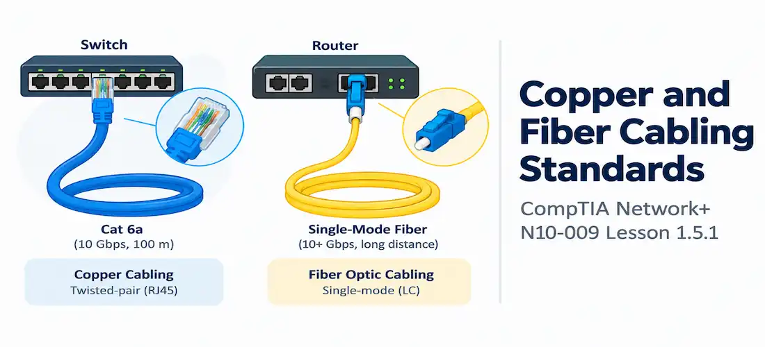
The overwhelming majority of copper network cabling in modern use is twisted-pair cabling — pairs of insulated copper wires twisted around each other specifically to reduce crosstalk (interference between adjacent pairs) and susceptibility to external electromagnetic interference.
The twisting itself is what makes this work: each pair carries the same signal as two opposite electrical currents, and twisting the pair together causes any external interference picked up along the cable’s length to affect both wires in the pair almost identically, allowing the receiving end to cancel that common interference out mathematically while preserving the actual intended signal, which appears as a difference between the two wires rather than a common value across both.
This is why simply running two parallel, untwisted copper wires side by side performs dramatically worse than the same wires twisted together — the twisting is doing real, load-bearing work, not just a manufacturing convention. Twisted-pair cabling is standardized into numbered categories, each supporting progressively higher speeds and/or longer distances than the last:
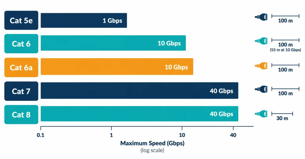
| Category | Max Speed | Max Distance (at rated speed) | Notes |
|---|---|---|---|
| Cat 5e | 1 Gbps | 100 meters | The long-standing baseline for Gigabit Ethernet; still common in older installations |
| Cat 6 | 1 Gbps (10 Gbps at reduced distance) | 100 meters (1 Gbps); ~55 meters (10 Gbps) | Improved crosstalk performance over Cat 5e |
| Cat 6a | 10 Gbps | 100 meters | “Augmented” Cat 6 — the standard baseline for reliable 10 Gigabit Ethernet at full distance |
| Cat 7 | 10 Gbps | 100 meters | Requires fully shielded construction; less common in typical office deployments |
| Cat 8 | 25/40 Gbps | 30 meters | Designed for short, high-speed data center connections rather than general office cabling |
Two details in this table are worth flagging specifically because they’re exactly the kind of nuance exam scenarios test: Cat 6 can technically support 10 Gbps, but only at a significantly reduced maximum distance (roughly 55 meters) compared to its full 100-meter rating at Gigabit speeds — this is precisely why Cat 6a, which reliably delivers 10 Gbps across the full standard 100-meter distance, became the practical baseline for new 10-gigabit copper installations rather than Cat 6 itself. And Cat 8’s distance limitation (just 30 meters) reflects its intended use case — short, high-speed runs within a data center rather than general-purpose office or campus cabling, where 100-meter runs are the norm.
UTP vs. STP: When Shielding Matters
Twisted-pair cabling comes in two shielding variants:
- UTP (Unshielded Twisted Pair) relies solely on the twisting of the wire pairs themselves to manage interference, with no additional shielding layer. It’s less expensive, more flexible, and easier to work with, making it the standard choice for the overwhelming majority of typical office and campus installations.
- STP (Shielded Twisted Pair) adds a metallic shielding layer around the twisted pairs (or around the entire cable), providing meaningfully better protection against external electromagnetic interference. This added protection comes at higher cost, reduced flexibility, and the added requirement of proper grounding for the shield to be effective at all — an improperly grounded STP installation can actually perform worse than UTP in some cases, since an ungrounded shield can itself act as an antenna, picking up and re-radiating interference rather than safely dissipating it away from the actual data-carrying conductors inside.
The decision between the two comes down to the electromagnetic environment a cable run will pass through: an ordinary office environment rarely justifies STP’s added cost and installation complexity, while an industrial environment with heavy machinery, large motors, or other significant sources of electromagnetic interference nearby is a much stronger candidate for STP’s additional protection.
Coaxial Cable: A Legacy Copper Standard
Coaxial cable — a central copper conductor surrounded by insulation, a metallic shield, and an outer jacket — predates twisted-pair Ethernet cabling and today survives primarily in two contexts relevant to Network+: as the last-mile connection for cable television and cable internet service (commonly RG-6 coax), and in certain specialized networking equipment connections.
Coaxial cable’s shielding design gives it good resistance to electromagnetic interference and made it historically well-suited to carrying broadband signals over the shared infrastructure cable providers use, where many households’ signals travel over portions of the same physical cable plant. While coaxial cable is far less central to modern Ethernet networking than it once was — twisted-pair and fiber have almost entirely displaced it for LAN connectivity — recognizing it and understanding its continued role in cable broadband delivery remains a testable fact, and it’s worth being able to identify a coax connector (typically a threaded F-connector) by sight, since it looks nothing like either an RJ45 or any of the fiber connectors covered later in this lesson.
Fiber Optic Cabling: Single-Mode vs. Multi-Mode
Fiber optic cabling carries data as pulses of light rather than electrical signals, offering advantages that become increasingly important as speed and distance requirements grow: fiber is immune to electromagnetic interference entirely (since it carries no electrical signal at all), supports dramatically longer distances than copper, and supports higher bandwidth. Fiber comes in two fundamentally different types, distinguished by the size of the glass core that actually carries the light:
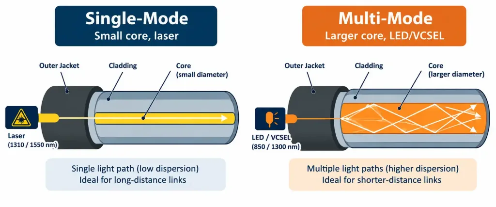
- Single-mode fiber (SMF) has a very small core (commonly 9 microns), narrow enough that light travels through it along essentially a single path. SMF typically uses a laser light source and supports the longest distances of any common cabling type — many kilometers without signal regeneration — making it the standard choice for long-haul, carrier, and campus-to-campus connections.
- Multi-mode fiber (MMF) has a larger core (commonly 50 or 62.5 microns), wide enough that light bounces along multiple different paths (modes) simultaneously as it travels. MMF typically uses an LED or VCSEL light source, which is less expensive than the laser sources SMF requires, but the multiple light paths spreading out over distance limit MMF to shorter maximum distances than SMF — typically hundreds of meters rather than kilometers, though this varies by specific standard and cable grade.
A widely used (though not universal) color convention helps distinguish the two at a glance in the field: single-mode fiber jacket is commonly yellow, while multi-mode fiber jacket is commonly orange or aqua, depending on the specific grade.
It’s worth contrasting fiber’s attenuation behavior with copper’s directly, since both experience signal loss over distance but for entirely different underlying reasons. Copper’s attenuation comes primarily from electrical resistance in the conductor itself, along with crosstalk and electromagnetic interference accumulating over distance — physical properties of carrying an electrical current through a metal conductor. Fiber’s attenuation comes from light scattering and absorption within the glass core itself as it travels, an entirely different physical phenomenon that happens to be far less severe over distance than copper’s electrical losses, which is the fundamental reason fiber supports such dramatically longer runs than copper before requiring signal regeneration.
Fiber Connector Types
Unlike twisted-pair copper cabling, which almost universally terminates in the familiar RJ45 connector, fiber optic cabling uses several distinct connector types, and Network+ expects you to recognize each by its general shape and typical application:
| Connector | Shape/Description | Typical Use |
|---|---|---|
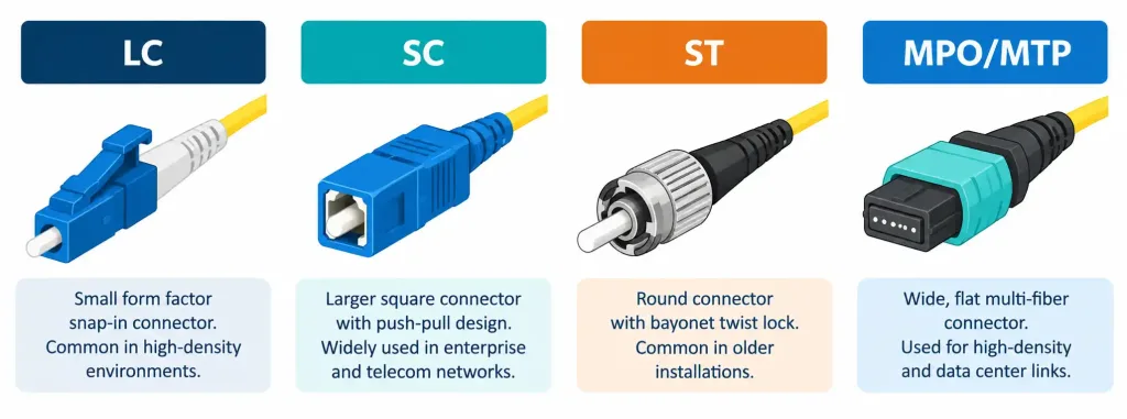
| LC (Lucent Connector) | Small form-factor, snap-in connector | The most common modern fiber connector, especially in high-density installations where physical space is limited |
| SC (Subscriber Connector) | Larger, push-pull square connector | An older but still common standard, particularly in existing installations |
| ST (Straight Tip) | Round, bayonet-style twist-lock connector | Common in older installations; largely superseded by LC and SC in new deployments |
| MPO/MTP | Multi-fiber push-on connector carrying many fiber strands in a single connector | High-density data center and backbone connections requiring many parallel fiber strands |
The general trend across fiber connector history has moved toward smaller, higher-density form factors — LC’s small size specifically exists to allow more fiber connections to fit within the same physical patch panel space compared to the larger SC and ST connectors, which matters enormously in data center environments where port density is often a genuine constraint. MPO/MTP connectors take this density trend even further by bundling many individual fiber strands (commonly 12 or 24) behind a single physical connector, which is then commonly split back out into individual LC or SC connections at each end using a breakout cable.
A practical technique that lets a single dense MPO trunk cable run through walls, conduits, or between racks, while still terminating in ordinary individual connectors at each device that actually needs one.
Choosing Between Copper and Fiber
The decision between copper and fiber for a given link comes down to a consistent set of trade-offs worth internalizing as a pattern rather than memorizing as isolated facts:
- Distance: Copper’s maximum distance (100 meters for standard twisted-pair Ethernet) is dramatically shorter than fiber’s, which easily reaches hundreds of meters (multi-mode) to many kilometers (single-mode) without needing signal regeneration.
- Cost: Copper cabling and the networking equipment that terminates it are generally less expensive than fiber cabling and its corresponding equipment, particularly for single-mode fiber and its laser-based optics.
- EMI immunity: Fiber’s complete immunity to electromagnetic interference (since it carries light, not electricity) makes it the clear choice in electrically noisy environments where copper’s performance could be compromised.
- Bandwidth: Fiber generally supports higher bandwidth over longer distances than copper, particularly as speed requirements climb into the tens or hundreds of gigabits.
In practice, this means most organizations use a mix of both: copper for shorter runs to individual end-user devices — often the same switches covered in Lesson 1.2.1, including PoE-capable ports powering access points along the way — and fiber for longer backbone runs between buildings, floors, or data center racks (where its distance and bandwidth advantages justify the added cost). This mixed approach recurs throughout real network designs precisely because the trade-offs aren’t uniform across an entire network — the same organization can make a perfectly reasonable case for copper in one part of its infrastructure and fiber in another, based purely on that specific link’s distance, budget, and interference environment, without either choice being “wrong” for the network as a whole.
A Complete Example: Cabling a Small Campus
Consider a small business campus with two buildings roughly 300 meters apart, each with several floors of offices. Within each floor, individual employee workstations connect to a wiring closet using Cat 6a UTP, staying comfortably within twisted-pair’s 100-meter distance limit while providing reliable 10 Gigabit capacity for future growth, and running some of these cables through ceiling plenum spaces means specifying plenum-rated cable to satisfy fire code.
Between floors within the same building, a riser-rated fiber backbone (likely multi-mode, given the relatively short distance involved) connects each floor’s wiring closet back to a central distribution point, terminated with LC connectors to conserve valuable patch panel space in a data closet with many other connections. Between the two buildings, spanning the full 300 meters, single-mode fiber is the only realistic choice, since that distance is far beyond both twisted-pair copper’s and multi-mode fiber’s practical range — this inter-building link might use an MPO trunk cable if enough parallel fiber capacity is needed to support high-bandwidth inter-building traffic, breaking out to individual LC connections at each building’s termination point.
This single example demonstrates every concept covered in this lesson working together in one realistic design: category selection driven by required speed, jacket rating driven by the physical installation environment, fiber mode selection driven by distance, and connector selection driven by density requirements — none of these decisions made in isolation from the others.
Physical Handling: Bend Radius Matters for Fiber
One more practical distinction worth knowing: fiber optic cable is considerably more sensitive to physical handling than copper. Bending a fiber cable beyond its rated minimum bend radius can cause the light traveling inside to leak out at the bend point or scatter internally, degrading or even breaking the signal entirely — a failure mode that has no real equivalent in twisted-pair copper cabling, which tolerates far more aggressive bending, coiling, and general rough handling without meaningful performance impact.
This is a genuinely practical, not just theoretical, consideration during installation: fiber runs need to be planned with gentler bend paths and proper cable management in mind, and a fiber link that mysteriously stops working after a cable was run through a tight corner or crimped under a heavy object is a classic real-world troubleshooting scenario directly traceable back to this physical property.
Recognition-Level Verification Concepts
This objective is descriptive/comparative, so there’s no hands-on cable termination expected on the exam. It’s worth recognizing, at a glance, a few identifying details:
- A cable’s printed jacket markings typically identify its category (e.g., “CAT6A”) directly, which is the fastest way to identify twisted-pair cabling in the field.
- Fiber connector shape alone is usually sufficient to identify the connector type without needing to trace the cable back to its source equipment — LC’s small snap-in profile, SC’s larger square push-pull body, and ST’s round bayonet twist-lock are each visually distinct.
- Jacket color, while not a universal guarantee across every manufacturer, is often the fastest practical way to distinguish single-mode from multi-mode fiber during installation or troubleshooting without needing to check printed specifications — yellow for single-mode, orange or aqua for multi-mode, as covered earlier in this lesson.
- Plenum-rated cable typically has its rating printed directly on the jacket alongside its category, since verifying this rating before installation in a ceiling space is a genuine compliance requirement, not an optional best practice.
Common Exam Traps
- Cat 6 supports 10 Gbps only at a reduced distance (~55 meters), not the full 100-meter standard distance — don’t assume Cat 6 and Cat 6a are interchangeable for reliable full-distance 10-gigabit runs.
- STP is not automatically “better” than UTP. It requires proper grounding to be effective, costs more, and is less flexible — the right choice depends entirely on the electromagnetic environment, not a blanket assumption that more shielding is always an improvement.
- Single-mode fiber’s smaller core, not a larger one, is what allows its longer distance. It’s counterintuitive at first — a narrower core restricting light to a single path is what avoids the signal-spreading effect that limits multi-mode’s distance, not the other way around.
- Fiber connector type and fiber mode (single-mode vs. multi-mode) are independent facts — an LC connector, for example, can terminate either single-mode or multi-mode fiber; the connector shape tells you nothing on its own about which fiber type is behind it.
- Coaxial cable is not obsolete on the exam just because it’s less common in new Ethernet deployments — its continued role in cable broadband delivery remains a testable fact in its own right.
- Plenum and riser ratings are about fire safety and building code compliance, not electrical performance — don’t confuse a cable’s fire rating with its speed category or shielding; a cable can be Cat 6a and plenum-rated simultaneously, since these describe entirely different properties.
- MPO/MTP connectors bundle many fibers behind one connector — don’t mistake a single MPO connection for a single fiber strand; it typically represents 12 or 24 individual strands that get broken out to individual connectors elsewhere in the link.
Lesson 1.5.1 Practice Questions
Copper and Fiber Cabling Standards · 17 questions · Network+ N10-009, Domain 1.0
Which cable category is the practical baseline for reliably supporting 10 Gbps across the full standard 100-meter distance?
A cable installer needs to run network cabling through a ceiling space used for HVAC air return. Which cable rating is required by building code?
Which statement correctly explains why single-mode fiber supports longer distances than multi-mode fiber?
Which two of the following are true about STP (Shielded Twisted Pair) cabling?
Based on this cable spec sheet, what is the maximum reliable distance for 10 Gbps operation?
A data center needs to run a very high density of fiber connections between racks, using individual fiber strands that terminate in small, space-efficient connectors. Which connector type is the best fit?
What does an MPO/MTP connector typically bundle behind a single physical connector?
Which two of the following are genuine advantages of fiber optic cabling over copper?
A fiber link that worked fine for months suddenly stops transmitting reliably after furniture was moved and the cable was crimped under a heavy filing cabinet in a tight corner. What is the most likely cause?
Which light source is typically associated with multi-mode fiber, as opposed to single-mode?
Based on this cable jacket label, what can be concluded?
A network architect needs to connect two buildings 300 meters apart. Which cabling type is realistically the only option?
What is the primary underlying cause of attenuation in copper cabling, as distinct from fiber?
Which two of the following correctly describe coaxial cable's role today?
An installer picks up a fiber patch cable with a yellow jacket. Based purely on this color convention, what type of fiber is it most likely to be?
Why is it incorrect to assume a fiber connector's shape tells you whether the fiber behind it is single-mode or multi-mode?
Based on this cable spec, which category does it most likely represent?
Summary
Twisted-pair copper cabling is standardized into categories (Cat 5e through Cat 8), each supporting progressively higher speeds and/or shorter maximum distances, with Cat 6a serving as the practical baseline for reliable full-distance 10 Gigabit Ethernet
UTP is the standard, lower-cost choice for typical environments; STP adds shielding for electromagnetically noisy environments, but requires proper grounding to be effective and costs more
Coaxial cable predates twisted-pair Ethernet and survives today primarily in cable broadband delivery
Single-mode fiber uses a small core and laser light source for the longest distances; multi-mode fiber uses a larger core and LED/VCSEL light source for shorter distances at lower cost
Common fiber connectors (LC, SC, ST, MPO/MTP) are distinguished by shape and typical application, with LC's small form factor now the most common choice in high-density modern installations
The choice between copper and fiber for a given link balances distance, cost, EMI immunity, and bandwidth needs, and most organizations use both together depending on the specific run's requirements