Domain 1.0 | Networking Concepts — 23% of exam
Learning Objectives
By the end of this lesson, you will be able to:
- Explain what VLSM is and why it beats equal-sized subnetting when requirements vary
- Work through a full VLSM design given a set of different host requirements
- Explain why subnets get allocated largest-first
- Check a VLSM design for address overlap
Key Terms – VLSM and Subnetting
| Term | Definition |
|---|---|
| VLSM (Variable Length Subnet Masking) | Subnetting where different subnets carved from the same address block use different prefix lengths, sized to what each one actually needs |
| Largest-First Allocation | The practice of assigning the biggest subnet requirement first, before smaller ones, to avoid fragmenting the address space |
| Address Overlap | When two subnets’ ranges accidentally intersect — a design error that breaks routing |
Explanation
The Problem VLSM Solves
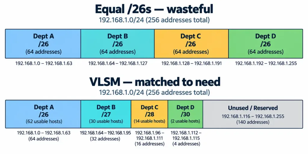
Lesson 1.7.2 ended with a specific complaint. Split a /24 into four equal /26s, and every department gets the same 62 hosts — whether they have 5 people or 55. That’s wasteful. VLSM fixes it by letting each subnet be exactly the size it needs, all carved out of the same original block.
The math behind VLSM isn’t new — it’s the same 2^n − 2 formula from the last lesson, applied over and over. What’s different is the process: instead of picking one prefix length and applying it everywhere, you work through each requirement individually, picking the smallest prefix that still fits.
The Rule That Makes It Work: Largest First
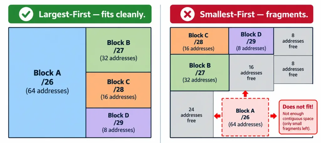
Here’s the one rule that makes VLSM actually work cleanly: always allocate your biggest requirement first.
Why? Picture doing it backwards — smallest first. You carve out a tiny subnet, then a slightly bigger one, and by the time you get to your largest requirement, the remaining address space might be fragmented into pieces too small and too scattered to fit it. Starting with the biggest block and working down avoids that entirely. Each subnet gets carved from what’s left after the previous, larger ones are already placed.
See what goes wrong concretely. Suppose someone works through the same four departments smallest-first instead: Department D (2 hosts) gets 192.168.1.0/30 first, then Department C (10 hosts) gets 192.168.1.4/28 — except a /28 needs to start on a boundary divisible by 16, and .4 isn’t one of those boundaries. The allocator has to skip ahead to the next valid /28 boundary, wasting the addresses in between.
Do this a few more times, and by the time Department A’s 50-host requirement comes up, the remaining space is scattered across several small, non-contiguous leftover chunks — none of them big enough to hold a single /26 block. The whole design has to be scrapped and redone. Largest-first sidesteps this entirely, because each new block only ever has to fit into whatever contiguous space remains after the bigger ones are already locked in.
A Full Worked Example
A company has four locations connecting into one /24 — 192.168.1.0/24 — and each needs a different number of usable addresses:
- Department A: 50 hosts
- Department B: 20 hosts
- Department C: 10 hosts
- Department D: a point-to-point link, 2 hosts
Sorted largest to smallest: 50, 20, 10, 2. Now work through them one at a time.
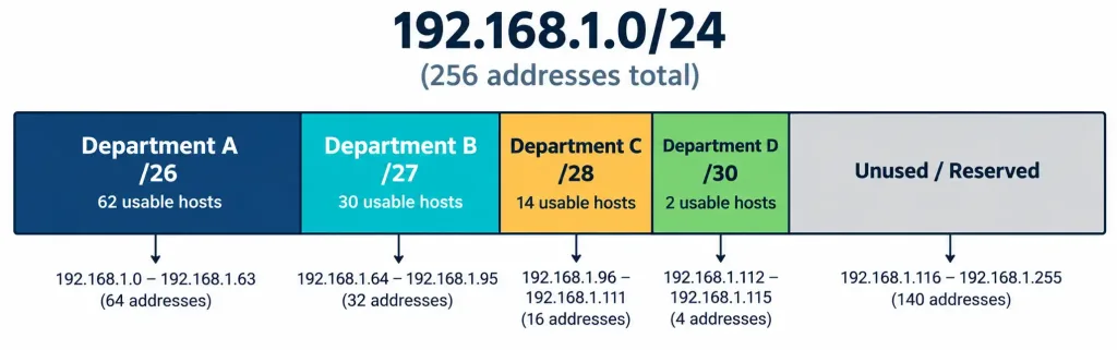
Department A needs 50 hosts. A /26 gives 62 usable (2^6 − 2), the smallest prefix that still covers 50. Assign 192.168.1.0/26 — range .0 through .63.
Department B needs 20 hosts. A /27 gives 30 usable (2^5 − 2), enough for 20 with room to spare. Starting right after Department A’s block ends, assign 192.168.1.64/27 — range .64 through .95.
Department C needs 10 hosts. A /28 gives 14 usable (2^4 − 2). Assign 192.168.1.96/28 — range .96 through .111.
Department D needs 2 hosts, for a point-to-point link. A /30 gives exactly 2 usable (2^2 − 2). Assign 192.168.1.112/30 — range .112 through .115.
| Department | Hosts Needed | Prefix | Range | Usable Hosts |
|---|---|---|---|---|
| A | 50 | /26 | 192.168.1.0 – .63 | 62 |
| B | 20 | /27 | 192.168.1.64 – .95 | 30 |
| C | 10 | /28 | 192.168.1.96 – .111 | 14 |
| D | 2 | /30 | 192.168.1.112 – .115 | 2 |
Add it up: 64 + 32 + 16 + 4 = 116 addresses used out of 256 total in the original /24. That leaves 192.168.1.116 through .255 — 140 addresses — sitting free for future growth. Compare that to equal /26 subnetting, which would have burned the entire /24 on just four 62-host blocks, wasting enormous amounts of space on Department D’s two-address point-to-point link alone.
Checking Your Work: No Overlap Allowed
Before calling a VLSM design done, walk the ranges and confirm none of them touch. In the example above: A ends at .63, B starts at .64 — no gap, no overlap, clean handoff. B ends at .95, C starts at .96. C ends at .111, D starts at .112. Every block picks up exactly where the last one left off, with zero wasted addresses between them and zero addresses claimed twice.
An overlap is a real design failure, not just an inefficiency. Two devices in “different” subnets that actually share an overlapping address range will cause routing chaos — traffic meant for one subnet gets confused with traffic meant for the other. Checking for overlap by hand, at least until it becomes second nature, is worth the extra minute every single time.
A Second Example, Just the Numbers
One worked example builds familiarity; a second one builds confidence. Suppose a smaller company needs three subnets out of 10.0.0.0/24: one for 100 users, one for 40 users, one for a 2-host management link.
Largest first. 100 hosts needs a /25 (2^7 − 2 = 126 usable) — assign 10.0.0.0/25, covering .0 through .127. Next, 40 hosts needs a /26 (2^6 − 2 = 62 usable) — assign 10.0.0.128/26, covering .128 through .191. Finally, the 2-host link needs a /30 — assign 10.0.0.192/30, covering .192 through .195.
| Requirement | Hosts Needed | Prefix | Range |
|---|---|---|---|
| Users, Group 1 | 100 | /25 | 10.0.0.0 – .127 |
| Users, Group 2 | 40 | /26 | 10.0.0.128 – .191 |
| Management link | 2 | /30 | 10.0.0.192 – .195 |
Same process, same largest-first discipline, different numbers. That’s really the whole skill — once the pattern clicks, the specific host counts in front of you stop mattering much.
One more detail worth flagging, even though the full mechanics belong to later routing content: not every routing protocol can actually carry VLSM information across the network. A modern, classless routing protocol includes the subnet mask alongside every route it advertises, so other routers know exactly where each VLSM subnet’s boundary falls.
Older, classful protocols don’t carry that mask information at all — they assume every subnet within a network uses the same mask, which breaks VLSM designs the moment a router running one of those older protocols tries to route between differently sized subnets. This is part of why classless routing protocols became the standard as VLSM adoption grew — the addressing scheme and the routing protocol carrying it need to agree on how much detail actually gets shared.
Where VLSM Shows Up in Practice
This isn’t just an exam exercise. Recall the VPC subnets from earlier in this course — a public-facing web tier and a private database tier inside the same VPC almost never need the same number of addresses, and cloud providers expect you to size each subnet accordingly rather than splitting everything evenly. The same logic applies to the layered architectures from Lesson 1.6.2 — an access-layer subnet full of end-user devices and a tiny point-to-point link between two core routers have wildly different address needs, and VLSM is exactly how a real network accommodates both out of the same overall address plan.
Recognition-Level Verification Concepts
This objective is mostly about doing the calculation correctly, but a few things are worth recognizing quickly:
- A VLSM design table listing several subnets with different prefix lengths, all carved from the same parent block, is exactly what this lesson has been building toward — recognize the pattern, then verify the math.
- Contiguous, non-overlapping ranges (one subnet’s last address immediately followed by the next subnet’s first address) is the signature of a correctly built VLSM design.
- Leftover, unused space at the end of the block isn’t a mistake — it’s healthy headroom for future growth, exactly like the 140 addresses left over in the worked example above.
Common Exam Traps
- Always allocate the largest requirement first. Working smallest-to-largest is the single most common way a VLSM design goes wrong, risking a large block that no longer fits cleanly.
- Each VLSM subnet still follows the 2^n − 2 rule on its own. Don’t forget to subtract the network and broadcast address for every individual subnet in the design, not just the original block as a whole.
- Unused leftover space at the end of a VLSM design is normal, not a failure. A good design doesn’t have to consume every single address in the original block.
- Overlapping ranges are a hard failure, not a minor inefficiency. Always check that one subnet’s range ends exactly where the next one begins, with no gap and no overlap.
- VLSM and equal-sized subnetting solve the same underlying problem differently — equal-sized is simpler but wasteful when needs vary; VLSM takes more calculation but matches the address plan to actual requirements.
- VLSM needs a classless routing protocol to actually work across a network. A classful routing protocol that doesn’t advertise subnet masks alongside routes can’t correctly route between differently sized VLSM subnets — the addressing scheme and routing protocol have to match.
Lesson 1.7.3 Practice Questions
VLSM and Subnetting Practice · 17 questions · Network+ N10-009, Domain 1.0
What does VLSM stand for?
In a VLSM design, which requirement should be allocated first?
A network needs a subnet for 50 hosts. Based on the prefixes below, which is the smallest one that fits?
Which two of the following are true about a correctly built VLSM design?
An engineer allocates subnets smallest-first and finds that a large 50-host requirement no longer fits into any single contiguous block of remaining address space. What went wrong?
Based on this VLSM design, is there an overlap problem?
Why is leftover, unused address space at the end of a VLSM design not considered a design flaw?
Which two of the following correctly describe why classful routing protocols cause problems with VLSM?
A company needs subnets for 100 hosts, 40 hosts, and a 2-host management link, all from 10.0.0.0/24. Following largest-first allocation, what is the first subnet assigned?
Following the same 100/40/2 host scenario, if the 100-host subnet is 10.0.0.0/25 (ending at .127), where should the 40-host /26 subnet begin?
Compared to splitting a /24 into four equal /26 subnets, what is the main advantage of VLSM when host requirements vary widely?
Which two statements about a cloud VPC using VLSM-style subnetting are accurate?
A design allocates 192.168.1.0/26, 192.168.1.64/27, 192.168.1.96/28, and 192.168.1.112/30. What address range is left unused at the end of this /24?
Which formula still applies to each individual subnet within a VLSM design?
An architect needs subnets for a core-layer point-to-point link (2 hosts) and an access-layer subnet with 200 end-user devices, both carved from the same block. What does VLSM allow that equal-sized subnetting doesn't?
Why is checking for address overlap considered essential before finalizing a VLSM design?
Based on this partial VLSM design, what prefix should be assigned to Subnet C, which needs 10 hosts?
Summary
VLSM lets subnets carved from the same address block use different prefix lengths, sized to what each one actually needs, avoiding the waste of equal-sized subnetting.
Always allocate the largest host requirement first, then work down to the smallest, to avoid fragmenting the address space.
Each subnet in a VLSM design still follows the standard 2^n − 2 usable-host formula on its own.
A correct VLSM design has contiguous, non-overlapping ranges, with any leftover space simply reserved for future growth.
VLSM shows up constantly in real designs — cloud VPC subnets and layered network architectures both rely on differently sized subnets carved from one larger address plan.