Domain 1.0 | Networking Concepts — 23% of exam
Learning Objectives
By the end of this lesson, you will be able to:
- Describe the purpose of layered networking models and why the industry uses them instead of treating networking as one monolithic process
- List all seven layers of the OSI model in order, state the function of each, and identify the Protocol Data Unit (PDU) associated with each layer
- List the four (or five) layers of the TCP/IP model and map them accurately onto their corresponding OSI layers
- Explain encapsulation and de-encapsulation, and trace how a single unit of application data is transformed as it moves down and back up the stack
- Identify which network devices and protocols typically operate at each layer, and use that mapping to reason about troubleshooting and traffic flow
Key Terms
| Term | Definition |
|---|---|
| OSI Model | A seven-layer conceptual framework (Physical, Data Link, Network, Transport, Session, Presentation, Application) used to describe how network communication functions are divided and organized |
| TCP/IP Model | The practical four-layer (sometimes described as five-layer) model that the modern Internet and most real-world networks actually run on: Network Access, Internet, Transport, Application |
| PDU (Protocol Data Unit) | The name given to a unit of data at a specific layer of the model — for example, a Segment at the Transport layer or a Frame at the Data Link layer |
| Encapsulation | The process of wrapping data with layer-specific header (and sometimes trailer) information as it moves down the stack, from Application toward Physical |
| De-encapsulation | The reverse process — stripping off headers/trailers layer by layer as data moves up the stack on the receiving device |
| MAC Address | A 48-bit hardware address burned into a network interface card, used for Data Link layer (Layer 2) addressing |
| IP Address | A logical address used for Network layer (Layer 3) addressing and routing between networks |
| Port Number | A 16-bit value used at the Transport layer to identify which application or service on a host should receive incoming data |
| Socket | The combination of an IP address and a port number, uniquely identifying a single communication endpoint |
| Protocol Suite | A collection of protocols that work together across multiple layers to accomplish end-to-end communication (e.g., the TCP/IP suite) |
Explanation
Why Networking Uses Layered Models at All
Imagine trying to design, troubleshoot, and manufacture networking equipment if every vendor built devices that handled “networking” as one giant, undivided blob of logic. A change to how cables carry electrical signals would force a redesign of the software that renders a web page. A bug in an application would be indistinguishable from a bug in the cabling. Nobody could specialize, interoperate, or troubleshoot efficiently.
Layered models solve this by breaking the overall problem of “get data from Application A on Host 1 to Application B on Host 2” into a stack of smaller, well-defined jobs. Each layer:
- Performs one specific function (e.g., “get bits onto the wire” or “choose the best path across networks”)
- Only needs to know how to talk to the layers directly above and below it
- Can be developed, replaced, or troubleshot independently, as long as it honors the interface contract with its neighboring layers
This is the same principle used throughout engineering: a car’s electrical system doesn’t need to know how the transmission shifts gears, but the two systems still work together through well-defined interfaces. Networking’s two dominant layered models are the OSI model (mostly theoretical/reference today, but essential shared vocabulary) and the TCP/IP model (what actually runs the modern Internet).
Network+ candidates are expected to know both models cold — not because you’ll type “OSI” into a router, but because every troubleshooting conversation, every vendor datasheet, and every exam scenario question uses layer numbers as shorthand (“that’s a Layer 2 problem,” “check Layer 3 connectivity first”).
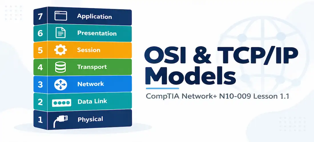
The OSI Model: Seven Layers
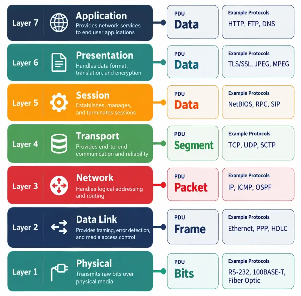
The Open Systems Interconnection (OSI) model was developed by the International Organization for Standardization to provide a vendor-neutral reference for describing network communication. It has seven layers. A widely used mnemonic to memorize them from Layer 7 down to Layer 1 is “All People Seem To Need Data Processing”, and from Layer 1 up is “Please Do Not Throw Sausage Pizza Away.” Pick whichever direction sticks better — the exam will test you both ways.
Layer 7 — Application This is the layer closest to the end user — but it is not the application program itself (like a web browser). Instead, it’s the layer that provides network services to applications: the protocols that let a browser request a web page, an email client send a message, or a file transfer utility move a document. Common protocols living here include HTTP/HTTPS, FTP, SMTP, DNS (functionally), and DHCP (functionally). PDU: Data.
Layer 6 — Presentation Responsible for translating, formatting, encrypting, and compressing data so that the Application layer on the receiving end can interpret it correctly. This layer handles character encoding (ASCII, Unicode), data formatting (JPEG, MP4, ASCII vs. EBCDIC), and encryption/decryption (SSL/TLS is often described as straddling Presentation and Session). Think of it as the “translator” — it makes sure two systems that might represent data differently internally can still understand one another. PDU: Data.
Layer 5 — Session Establishes, manages, and terminates the communication session (dialogue) between two hosts. It handles things like session checkpoints, dialogue control (who talks when — full-duplex vs. half-duplex), and session recovery after an interruption. Protocols and APIs like NetBIOS, RPC (Remote Procedure Call), and PPTP tunnel-session-establishment logic are commonly cited examples. PDU: Data.
Layer 4 — Transport This is where end-to-end communication reliability decisions are made. The Transport layer is responsible for segmenting data from the upper layers into manageable chunks, adding port numbers to identify the correct application/service, and — critically — choosing between connection-oriented delivery (TCP) with error recovery, sequencing, and flow control, versus connectionless delivery (UDP) with no such guarantees but far lower overhead. This is one of the single most heavily tested concepts on the exam. PDU: Segment (TCP) or Datagram (UDP).
Layer 3 — Network Responsible for logical addressing and path determination — in other words, routing. This is where IP addresses live, and where routers make forwarding decisions based on destination network addresses rather than physical hardware addresses. Protocols here include IPv4, IPv6, ICMP, and routing protocols like OSPF and BGP (their control-plane traffic operates using Layer 3 addressing even though the protocols themselves have their own logic). PDU: Packet.
Layer 2 — Data Link Handles node-to-node data transfer on the same physical/logical segment, using physical (MAC) addressing rather than logical (IP) addressing. This layer is commonly split conceptually into two sublayers: LLC (Logical Link Control), which interfaces with Layer 3 and handles flow control/error checking, and MAC (Media Access Control), which handles physical addressing and controls how devices access the shared medium. Switches operate primarily at this layer, forwarding frames based on MAC address tables. Protocols/technologies here include Ethernet, 802.1Q VLAN tagging, and ARP (functionally bridges Layer 2/3). PDU: Frame.
Layer 1 — Physical The lowest layer, dealing with the actual transmission of raw bits over a physical medium — electrical voltages on copper cabling, light pulses over fiber, or radio waves over wireless. This layer defines cable types, connectors, pinouts, voltage levels, and the physical/electrical/mechanical specifications for network hardware. Hubs and repeaters, along with cabling itself, operate here. PDU: Bits.
The TCP/IP Model
While the OSI model is the standard reference framework used for teaching and discussing networking, the protocol suite that actually powers real-world networks — including the Internet — is the TCP/IP model. It predates the OSI model’s formalization and was built pragmatically around the protocols DARPA needed for early internetworking, which is why it has fewer, broader layers.
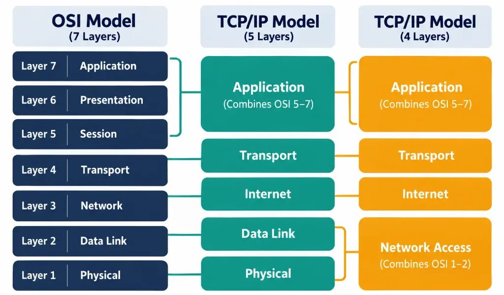
The classic TCP/IP model has four layers:
- Application — combines the functions of OSI’s Application, Presentation, and Session layers into one. Protocols: HTTP/HTTPS, FTP, SMTP, DNS, DHCP, SSH, Telnet.
- Transport — functionally identical in purpose to OSI’s Transport layer. Protocols: TCP, UDP.
- Internet — maps to OSI’s Network layer. Protocols: IPv4, IPv6, ICMP.
- Network Access (also called Link or Network Interface) — combines OSI’s Data Link and Physical layers into one. Covers Ethernet, Wi-Fi, and the physical media itself.
Some newer textbooks (and some exam objectives) describe a five-layer TCP/IP model that splits Network Access back into separate Data Link and Physical layers, producing a model that lines up one-to-one with OSI Layers 1 through 4, while still merging OSI Layers 5–7 into a single Application layer. Either representation is valid — know both, because exam questions sometimes reference “the TCP/IP model” without specifying which version, and the correct answer usually depends on context (e.g., a question mentioning “cabling issues” implies the five-layer view where Physical is distinct from Data Link).
Side-by-Side Comparison
| OSI Layer | OSI Name | TCP/IP (5-layer) | TCP/IP (4-layer) | PDU |
|---|---|---|---|---|
| 7 | Application | Application | Application | Data |
| 6 | Presentation | Application | Application | Data |
| 5 | Session | Application | Application | Data |
| 4 | Transport | Transport | Transport | Segment/Datagram |
| 3 | Network | Internet | Internet | Packet |
| 2 | Data Link | Data Link | Network Access | Frame |
| 1 | Physical | Physical | Network Access | Bits |
A key exam-relevant takeaway: the OSI model’s Layers 5–7 (Session, Presentation, Application) don’t correspond to three cleanly separate real-world protocols the way Layers 1–4 do. In practice, protocols like HTTP handle what OSI would split across all three upper layers. This is precisely why OSI is described as a reference/teaching model rather than a model that maps one-to-one onto how software is actually built.
Encapsulation and De-Encapsulation
Encapsulation is the process by which data is wrapped in progressively more header (and, at Layer 2, trailer) information as it travels down the stack on the sending device, and de-encapsulation is the reverse process of stripping those headers off, one layer at a time, as data travels up the stack on the receiving device.
Walk through a concrete example — a user’s web browser requesting a page over HTTPS:
- Application/Presentation/Session (Layers 7-5): The browser generates the HTTP request and hands it, along with any TLS encryption applied at the Presentation-layer boundary, down as Data.
- Transport (Layer 4): TCP adds a header containing source and destination port numbers (destination 443 for HTTPS), sequence numbers, and flags. The data + TCP header is now called a Segment.
- Network (Layer 3): IP adds a header containing the source and destination IP addresses. The segment + IP header is now called a Packet.
- Data Link (Layer 2): Ethernet adds a header containing source and destination MAC addresses, plus a trailer (Frame Check Sequence, used for error detection). The packet + Ethernet header/trailer is now called a Frame.
- Physical (Layer 1): The frame is converted into bits — electrical signals, light pulses, or radio waves — and transmitted onto the medium.
On the receiving end, this process runs in exact reverse: bits are reassembled into a frame, the Layer 2 header/trailer is stripped and the MAC address is checked, the frame’s payload (now a packet) is passed up to Layer 3 where the IP header is examined and stripped, the resulting segment goes up to Layer 4 where the TCP header is examined (port number tells the OS which application/socket to deliver to) and stripped, and finally the raw Data reaches the receiving application.
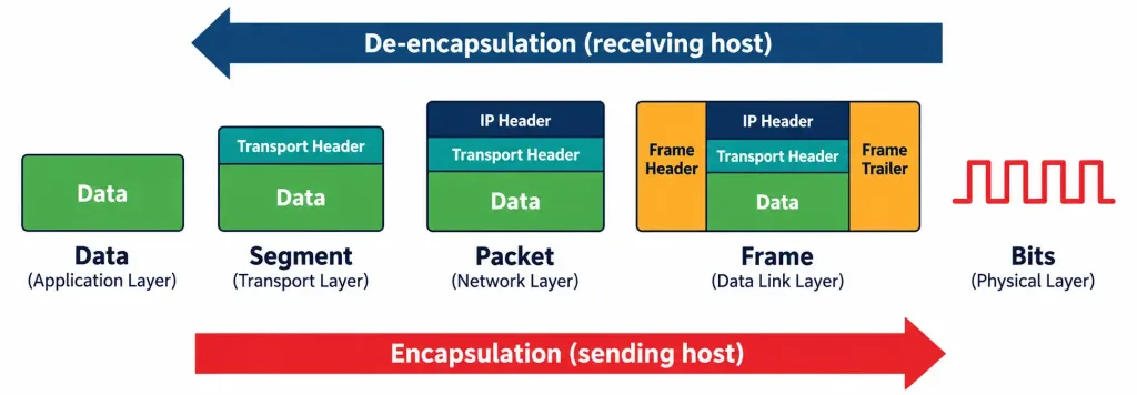
Understanding this sequence is essential for troubleshooting, because it tells you exactly what information is available — and what could be going wrong — at each stage. A switch cannot make a Layer 3 routing decision because it never looks past the Layer 2 header; a router cannot forward based on MAC address alone because its job starts at Layer 3, examining the IP header inside the packet.
Devices and Troubleshooting by Layer
One of the most exam-relevant (and real-world-relevant) reasons to know the model cold is that it gives you a systematic way to isolate problems. Network+’s troubleshooting methodology (covered fully in Lesson 5.1) explicitly encourages a layered approach — often informally called the “bottom-up” or “top-down” method.
| Layer | Typical Devices/Components | Typical Failure Symptoms |
|---|---|---|
| Physical (1) | Cabling, connectors, hubs, repeaters, transceivers | Link light out, no connectivity at all, intermittent drops from a bad cable |
| Data Link (2) | Switches, bridges, NICs, access points | MAC address table issues, VLAN misconfiguration, duplex mismatches |
| Network (3) | Routers, Layer 3 switches, firewalls (routing function) | Incorrect routing, wrong subnet mask, unreachable destination network |
| Transport (4) | Firewalls (port filtering), load balancers | Blocked ports, failed TCP handshakes, application timeouts |
| Session–Application (5-7) | Application servers, DNS servers, proxy servers | Application errors, DNS resolution failures, authentication failures |
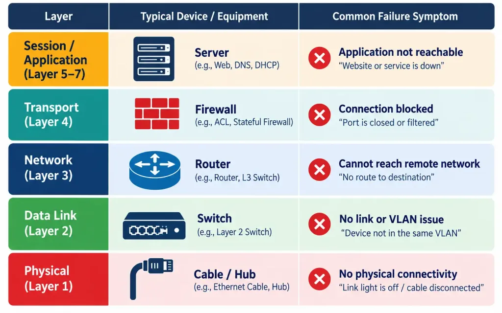
This table is worth internalizing rather than memorizing verbatim, because scenario-based exam questions frequently describe a symptom and ask you to identify which layer is the most likely culprit, or which device to check first.
Recognition-Level Command References
Domain 1.1 is conceptual rather than hands-on — you won’t be asked to configure anything here — but you should be able to recognize which layer a given diagnostic command primarily operates at, since this connects directly into Domain 5’s troubleshooting content:
ping— operates using ICMP at Layer 3, but its success/failure also implicitly depends on Layers 1-2 functioning correctly beneath itarp -a(orip neighon Linux) — displays the Layer 2-to-Layer 3 mapping table (MAC-to-IP)netstat— shows active Layer 4 connections (TCP/UDP) and the ports/sockets in usetraceroute/tracert— reveals the Layer 3 path (hop-by-hop) a packet takes to a destinationnslookup/dig— operate at Layer 7, resolving names via DNS
You’ll work with all of these hands-on later in Domain 5 (Lessons 5.5.1 and 5.5.2). For now, the goal is simply to associate each tool with the layer(s) it primarily reveals information about.
Common Exam Traps
- Don’t confuse “layer” with “device.” A firewall can inspect and act at multiple layers simultaneously (Layer 3 for IP filtering, Layer 4 for port filtering, and even Layer 7 for application-aware inspection on next-gen firewalls). Questions sometimes test whether you understand that modern devices aren’t strictly confined to one layer.
- Know the PDU names cold — Data, Segment/Datagram, Packet, Frame, Bits — because exhibit-based questions often show you a diagram or packet capture and ask “what is this unit of data called at this point in the process?”
- TCP/IP model layer counts vary by source — don’t panic if you see both 4-layer and 5-layer descriptions; understand what each version represents rather than memorizing a single “correct” number.
- Encapsulation direction matters — sending host encapsulates (adds headers going down); receiving host de-encapsulates (removes headers going up). Exam questions sometimes flip the scenario (e.g., “at the router, is the packet being encapsulated or de-encapsulated as it moves from the LAN interface toward the Network layer?”).
Lesson 1.1 Practice Questions
OSI & TCP/IP Models · 17 questions · Network+ N10-009, Domain 1.0
Which OSI layer is responsible for logical addressing and path determination between networks?
What is the correct term for a unit of data at the Data Link layer?
A network technician needs to explain why a switch cannot make forwarding decisions based on IP address alone. Which statement best explains this?
Which two layers of the OSI model are combined into the "Network Access" layer in the four-layer TCP/IP model?
Which layer of the OSI model adds port numbers to identify the correct destination application or service?
During encapsulation on a sending host, in which order is data transformed?
A packet capture shows a unit of data containing a source IP address of 10.0.0.5, a destination IP address of 10.0.0.20, and no MAC address or port number information visible. At which layer of the OSI model does this unit of data exist?
Which of the following best describes the relationship between the OSI and TCP/IP models?
A user reports that their computer has a valid IP address and can ping the default gateway, but cannot reach any websites by name. At which layer should troubleshooting most likely begin?
Which two protocols are examples of Transport layer protocols?
Which sublayer of the Data Link layer is responsible for physical/hardware addressing and controlling access to the shared medium?
A network engineer is designing documentation that describes how a firewall inspects both the destination port number of traffic and the actual application payload (application-aware filtering). Which two OSI layers is this firewall functioning at simultaneously?
Which PDU name is used specifically for data at the Transport layer when using UDP rather than TCP?
What is the primary purpose of the Presentation layer in the OSI model?
A student memorizing the OSI model uses the mnemonic "Please Do Not Throw Sausage Pizza Away." Which layer does "Sausage" represent?
Which two of the following operate primarily at Layer 1 (Physical)?
During de-encapsulation on a receiving host, a Frame has just had its Ethernet header and trailer removed. What is the resulting unit of data now called, and which layer will process it next?
Summary
Layered models (OSI and TCP/IP) exist to divide the overall job of network communication into independent, well-defined functions, enabling interoperability, specialization, and systematic troubleshooting
The OSI model's seven layers — Physical, Data Link, Network, Transport, Session, Presentation, Application — form the shared vocabulary of the networking industry, even though it's a reference model rather than what literally runs on the wire
The TCP/IP model (four or five layers, depending on the source) is what the modern Internet actually implements, and it maps onto OSI with Layers 5-7 merged into a single Application layer
Encapsulation adds layer-specific headers as data travels down the stack (Data → Segment/Datagram → Packet → Frame → Bits); de-encapsulation reverses this on the receiving end
Knowing which devices and protocols live at each layer gives you a systematic troubleshooting approach that will be built on heavily in Domain 5